|
CGS18 - Drum Simulator
This module is the embodiment of the classic twin-T circuit in a form that is suitable for connection to modular synthesizers. It contains two separate drum sounds, each individually triggered, as well as something unique - adjustable harmonic content. This updated version contains some minor changes. TL072 are used throughout. Hysteresis has been added to the trigger inputs. All connections are now in a single row, with strain-relief holes provided for the wires How to use this module: Connect the inputs to a LFO, a gate sequencer or some other rhythmic pulse source. Connect the outputs to a mixer, or feed them into some relevant part of the synthesizer. Adjust the harmonics from the basic sine tone to something rich in harmonics. A little on how it works: The schematic of the Drum simulator. Each of the two drums consists of three distinct blocks, the trigger, the ringing oscillator and the buffer/distortion amp. The trigger takes any positive going signal that goes over approximately 1.5 volts and converts it into a narrow positive going pulse. This pulse is fed to the reference ground of the ringing oscillator, de-stabilizing it, thus causing it to start oscillating. Depending on the resonance setting, the ringing oscillator output will decay until the circuit again reaches stability with no audio output. The output of the ringing oscillator is fed past a clipper consisting of a single LED, the current of which is limited by the series resistance of the 50k pot. The result is buffered by the inverting unity gain amplifier. The 22k/2k2 resistor combination at pin 3 of U2A and U3A controls the amount of DC that makes it through to the output of the drum simulators, simulating the impact sound. Reducing the 2k2 resistors will reduce the impact sound. Our kits include parts that allow you to replace the 2k2 resistors with a 1k linear pot (wired as a variable resistor) in series with a 680 ohm resistor so the level of the impact sound can be varied from the front panel. With the values shown above, the upper circuit will have a notch frequency covering the range ~47Hz to ~134Hz while the lower circuit will have a notch frequency range covering ~101Hz to ~285Hz. . Construction
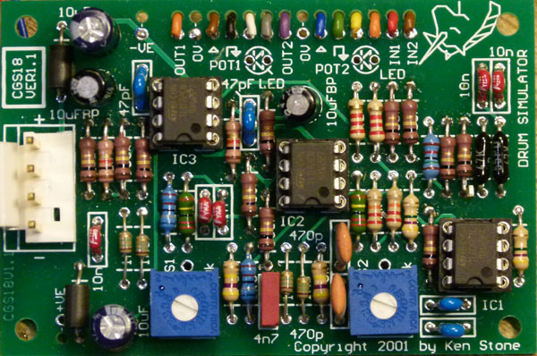
The component overlay. Connections can be determined from the circuit diagram. There are two 100n 1206 SMT decoupling capacitors on the rear of the board. When you power it up for the first time, you will need to adjust the resonance trimpots until the oscillators just stop oscillating. Do this with no trigger inputs.
Notes:
Article, art & design copyright 2001 by Ken Stone |