Reference Drive Current
-
Open JP1 and JP2
-
Monitor the [SAWTOOTH] output
-
Adjust P201 for a frequency of 880Hz
1V/OCTAVE Adjustment
-
Install JP2
-
Apply 0.00V to the [1V/OCTAVE] input
-
Monitor the frequency of the [SAWTOOTH] output
-
Turn P106 fully clockwise
-
Adjust P105 for an output frequency of 220Hz
-
Apply 3.00V to the [1V/OCTAVE] input
-
If the frequency is higher than 1800Hz then rotate P106 one full-turn counter-clockwise. If the frequency is between 1780Hz and 1800Hz then rotate P106 in quarter-turns clockwise, otherwise minor clockwise adjustments
-
This is an interative process. Do not try setting the upper frequency immediately to 1760Hz.
-
Repeat steps (4) to (8) until the settings are 220Hz respectively 1760Hz
PROCESSOR SPAN Adjustment
- Install JP1
- Monitor the [SAWTOOTH] output
- Set [FREQUENCY] and [FINE] to their centre positions
- Set the [VC F] pot to its minimum position
- Apply 1.0V to the [VC F] input
- Adjust P105 for a frequency of 100Hz (if you can't trim down to 100Hz then use the [FINE] control to drop the frequency below 100Hz and the use P105 to bring it back up)
- Set the [VC F] pot to its maximum position
- Adjust P103 for a frequency of 400Hz
- Repeat steps (4) to (8) until the full swing of [VC F] is as close to 100Hz ↔ 400Hz as possible
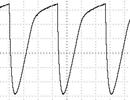
SAWTOOTH Adjustment
-
Monitor the [SAWTOOTH] output
-
Adjust P301 until the waveform is centred around 0V
WAVESHAPE Adjustment
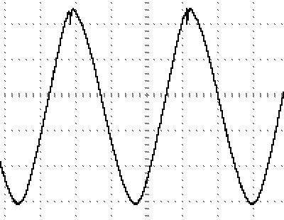
P401 should be adjusted so that the [VARIABLE] output varies between a ‘sine’ and a ‘sawtooth’ wave as the [SHAPE] control is adjusted.
A simpler alternative is to adjust this trimmer until the best symmetry between the peak and the trough is achieved at the [SINE] output (J402).
Don't expect a perfect waveform - it will most likely have a substantial glitch in it at its best setting.
Remember - this sine output is simply there to make use of a spare part of the LM3900 - it is not a key feature of the design.
STEPS Adjustment
-
Monitor the [SAWTOOTH] output
-
Adjust [FREQUENCY] and [FINE] for a frequency of 110Hz
-
Set P501 fully clockwise and P502 to fully counter-clockwise positions
-
Monitor the [STAIRCASE] output
-
Adjust P501 until the output jumps to just over 5V peak (NB: this is the [STEPS] control on the full version)
-
Adjust P502 until the frequency drops down to just below 15Hz
Remember this will not follow the oscillator over its entire range.
Again, it is simply there to make use of a spare part of the LM3900 - it is not a key feature of the design.
BASE Frequency Adjustment
This adjustments sets the range of output control with the [FREQUENCY] and [FINE] controls, with no CV inputs and allows multiple VCO's to have the same basic [FREQUENCY]/[FINE] settings.
The adjustment below will set the range from 125Hz to over 10kHz with [FINE] between mid-position and fully clockwise and from ~125Hz down to ~0.33Hz (1 cycle per 3 seconds) with [FINE] between mid-position and fully anti-clockwise.
-
Set [FREQUENCY] to its minimum position
-
Set [FINE] to its maximum-position
-
Apply 0VDC to the [1V/OCTAVE] input
-
Monitor the [SAWTOOTH] output
-
Adjust P105 for an output frequency of 125Hz