Twin CMOS VCF
UPDATED TO CGS349
This board containts two independant VCFs based on the popular CMOS based Wasp VCF, In adition it also features adjustable post-filter distortion.
A little on how it works:
Click here for the Schematic
Of note is that the filter core is running between 0V and -5V, allowing a simple exponential converter to be used to give an appropriate response to the control voltage. The distortion channel straight signal are mixed via a seque circuit (reverse panner). The final stage is just a regular, inverting amplifier, but with a voltage divider in the feedback loop to avoid the need for an excessively high value resistor to achieve the required gain.
Construction
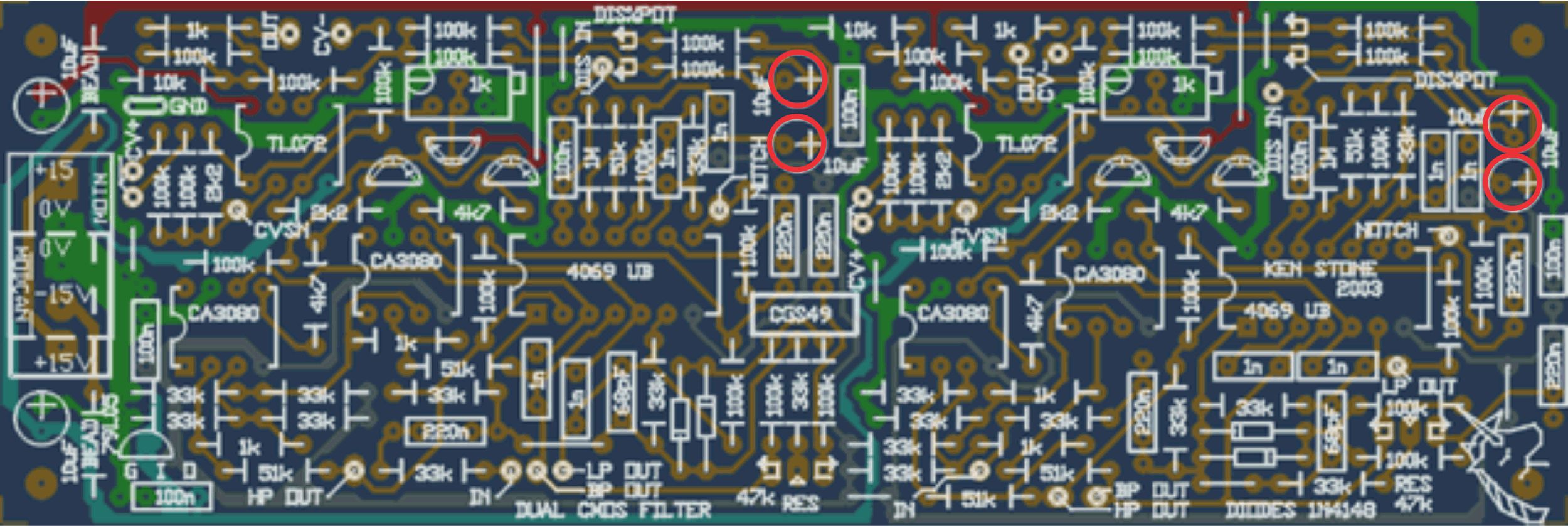
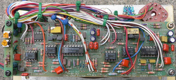
| The component overlay for the filter.
|
Take particular care with the orientation of the polarized components such as electrolytics, diodes, transistors and ICs.
The CMOS chip MUST be of the unbuffered type. 4069 continued to be made in UB form long after most other UB 4000 series chips were stopped, so locating them should not be difficult. CD, HEF etc. are acceptable designators. Do not use chips with designators starting with "74".
It has been suggested that connecting the frequency pot between +VE and -VE instead of +VE and GND as shown will allow the filter to be used at lower frequencies. If doing this, you may find it beneficial to change the wiper resistor up to 270k, or add an extra resistor of 150k in series with the wire from the wiper to the PCB.
Tuning. Set the trimmers for a 1 volt per octave response. It will never be as accurate as a VCO as there is no thermal compensation, so "close enough" is good enough.
The photo shows to additional 100k trimmers I added to allow centering of the frequency pots. They are wired between +VE and -VE, with 100k wiper resistors fed to the CVSN pads on each filter. Alternatively, the CCW end of the frequency pots could be wired to -VE (via resistor if needed) instead of to 0V.
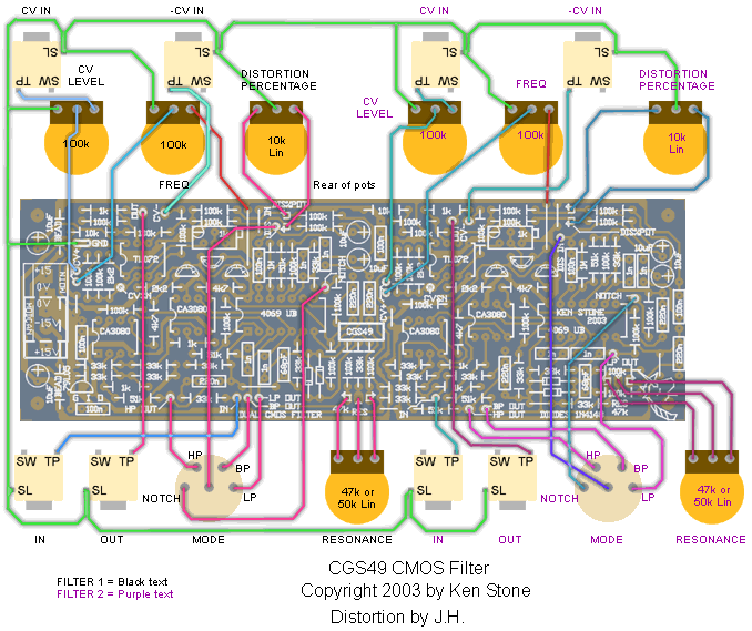
Suggested wiring for the filters.
Note: The CCW end of the frequency pots should be wired to -VE instead of to 0V as shown above
|
Notes:
-
The 4x 10uF capacitors (marked in red in the above pcb overlay) are incorrectly orientate on the pcb
-
TI chips (CD4069UBEE4) reportedly give greater distortion than some other brands of 4069.
-
If you get absolutely no response to CV, check that the trimmer for that filter is not set to the bottom of it's range.
-
The Distortion channel is based on Jurgen Haible's design. Filter originally by Chris Huggett.
-
PCB info: 2" x 6" with four 3mm mounting holes 0.15" in from the edges.
Parts list
This is a guide only. Parts needed will vary with individual constructor's needs.
Article, art & design copyright 2003 by Ken Stone
|