|
Analog Switch Matrix for music synthesizers.
The Analog Switch Matrix is a complex router, allowing one input to be switched between four outputs, or vice versa, or even to route one signal through one of four external effects (e.g. wave multipliers, filters etc.). It can also be used as four independent analog switches. All analog switches are independently addressed, so combinations of these arrangements are also possible. Further enhancing this is that the common input and output external are to the main switching matrix. There is also a separate mixer than can be used for recombining signals when routing between different effects, or the mixer can be used as an independent general purpose DC coupled unity gain mixer. The analog switch is DC coupled so can be used for both control voltages and audio signals. Suitable drivers for one-at-a-time switch control include the Gate Sequencer and the Weighted Random Switch. Any module, or combination of modules, that generates gate signals can be used to drive the matrix if having more than one switch closed at time is acceptable or desirable. The Weighted Random Switch is a companion module, as it can be directly connected while leaving the standard gate inputs functional. A little on how it works:
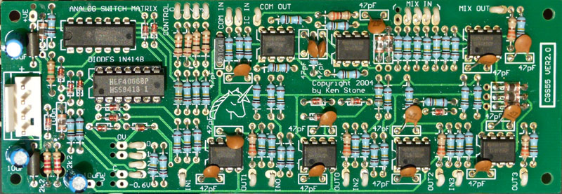
The schematic of the Analog Switch Matrix. How does a device (the 4066) that has only a 15v range allow at least +/-10V to pass through it? The answer is it doesn't. By powering the 4066 and its associated drive circuitry from +14.4V and -0.6V, and placing the output of the analog switch at the virtual ground point of an inverting op-amp buffer, the full range of the signal is allowed to pass while the voltage at that point is held near or at 0V by the action of the op-amp while the analog switch is closed. When the analog switch is open, the diode connected between the input and 0V prevents in incoming signal from going below -0.6V, and thus prevents it from going outside the allowed input range. There is no need to protect against excursions in the positive direction, as these are in the allowed input range. A second diode at the output of the analog switch prevents the op-amp from driving the output below -0.6V, should the switch open while such potential exists. Construction
Weighted Random Switch As mentioned, this switch matrix can be used to expand the switching capabilities of the Weighted Random Switch. Joining the two is relatively straight forward. On the CGS51 board there is an area of the board marked off with a thin line, containing the text "The Neurotic". All parts are to be omitted from this area as they are not needed. There are numerous pads around this area marked with a white outline. Of interest are those marked 0, 1, 2, 3, and C. These connect directly to the corresponding pads on the CGS55 board, thus linking the two together. It is possible to omit the power supply parts from one of the two PCBs and link the pads marked +VE, -VE, 0V and -0.6V as well. If it is easier, there is no reason why the power supply parts can't be installed on both boards, with each board being fed via its power connector. These pads line up on the two boards, so it would be possible to mount the boards one on top of the other, with a plug and socket arrangement between the two boards to allow easy servicing. These plugs and sockets could be made from machine socket pins or similar. Again, this is only optional, and simply running insulated wires between the corresponding pads may prove more reliable and easier to build. A switch could be placed between the C pads, allowing the switch matrix to be isolated from the weighted random board when the switch matrix is needed without the random function. Notes:
Parts list This is a guide only. Parts needed will vary with individual constructor's needs. Article, art & design copyright 2003 by Ken Stone |