|
Active Real Ring Modulator UPDATED TO CGS367 
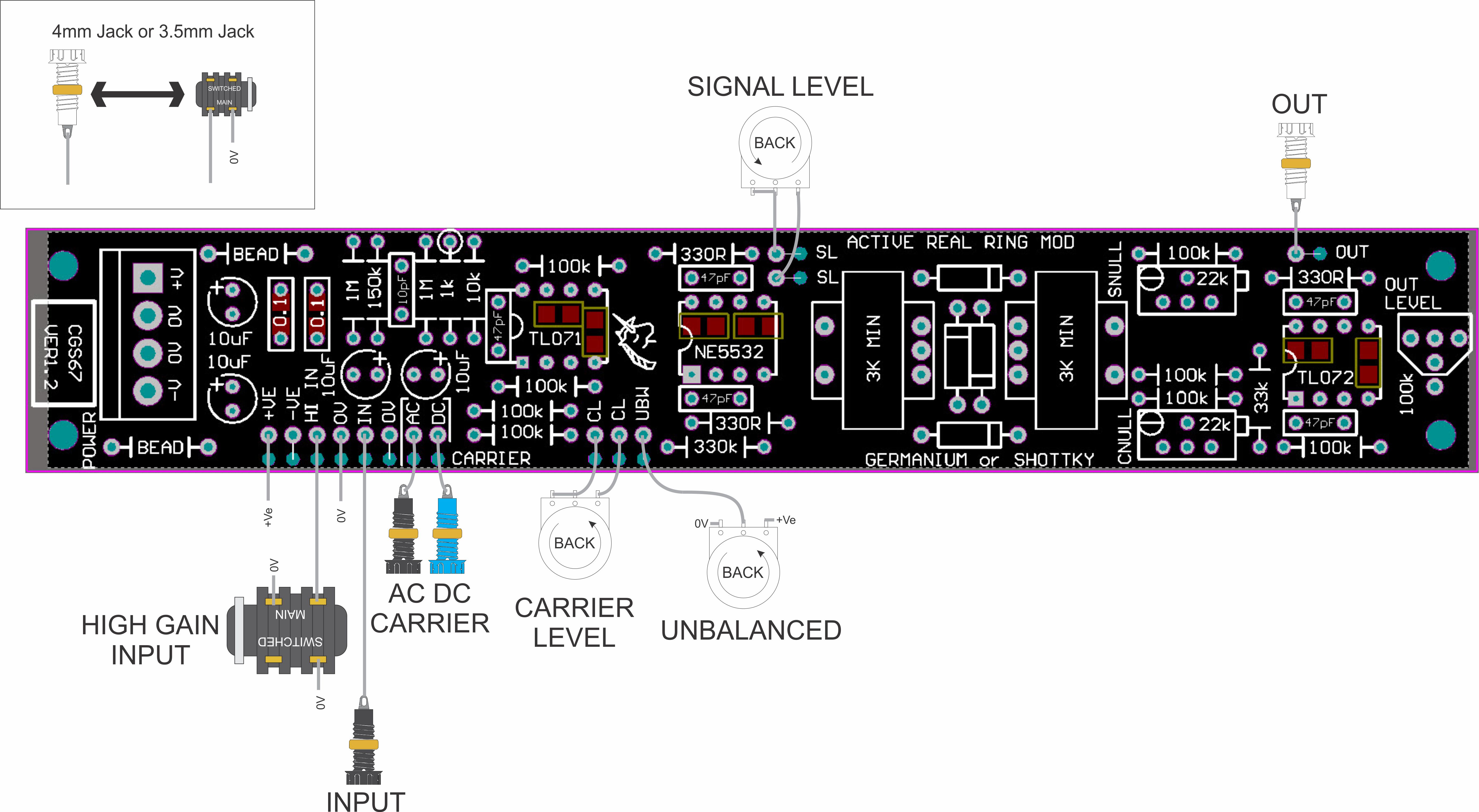
Four quadrant multipliers have more or less replaced ring modulators in synthesizers, even though they still bear the label "ring modulator". The distortion in these is lower than that of a true diode ring modulator, because the diode voltage drops have been eliminated. This leads to better specifications, though in a noise maker, this is not always desirable. Here is an updated version of the popular "Real Ring Modulator", a traditional diode and transformer ring modulator. This time, a preamplifier for external input, and input and output buffers for conventional synthesizer levels are included. A little on how it works.There are several distinct sections to this circuit. A TL071 op amp is wired as a high input impedance 10x gain stage for dealing with small signals such as from microphones and electric guitars, though the latter's output is probably hot enough to drive the stage into distortion. The NE5532 is wired as two adjustable, low output impedance buffers for driving the transformer coils of the ring modulator itself. They only differ in the upper one mixes the above pre-amp output with a synth level input, while the other has three inputs - two DC coupled, and one AC coupled. One of the DC coupled inputs is wired to a pot to allow a DC voltage to be fed into the modulator to unbalance it, thus changing its characteristics. The unbalance function is not unlike a wet/dry mixer. The core of the circuit is of course the passive ring modulator, consisting of two transformers and four diodes in a ring. Traditionally these diodes should be germanium, though schottky diodes such as the BAT48 can be used. Even 1N4148 silicon diodes will work, though with greater distortion due to the larger voltage drop. Following the core is a nulling circuit. The circuit allows either a positive or negative portion of the original carrier and input signals to be mixed with the output to reduce the amount of bleed though. If this is not desired, the trim pots can simply be left off the board. Finally there is an output buffer and recovery amp. The 100k resistor marked with an asterisk on the schematic should be a lot lower - say 33k, or even as low as 10k, if you find you do not have enough gain. This will depend on the transformers used. With the 100k shown, the maximum gain is unity. Construction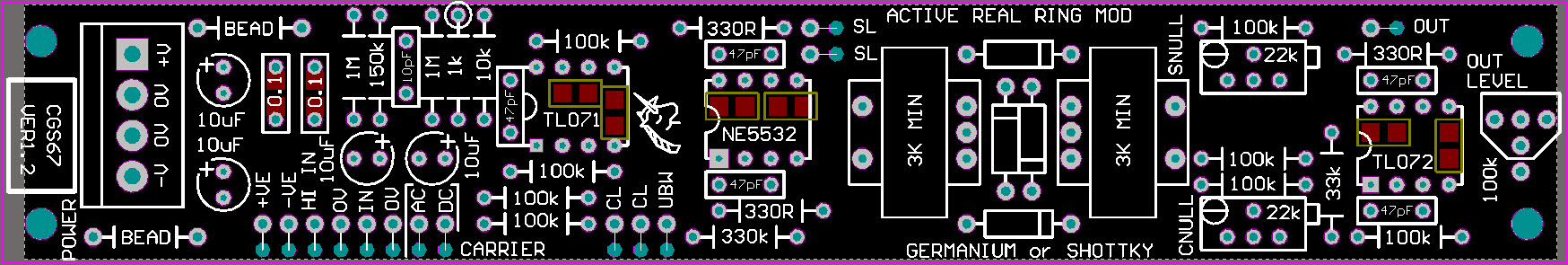
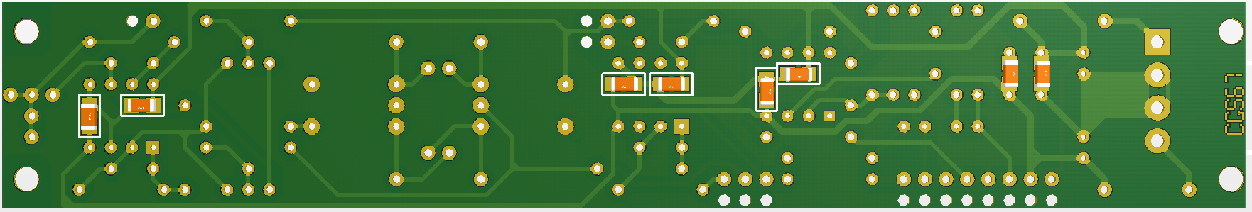
The decoupling capacitors used are SMT1206 variety, though 0805 can fit. Two of the locations (far right) are optional and can either be a through hole component (as per the BOM) or SMT. The part number of the Germanium diodes is not critical. Use whatever you can get. The transformer used is an "M0222" 3k-3kCT coupling transformers from www.altronics.com.au. Other transformers will work in this circuit. You will want transformers with an impedance equal to or higher than these. Setting upIf the unbalance pot is fitted, turn it fully CCW, checking with a meter that it's wiper is at zero volts.
Feed an audible signal into the input, and monitor the output. Adjust the [SNULL] trimmer for minimum output volume. It will be near the center of the trimmer's travel. Remove the signal from the input and feed it into the [AC] coupled carrier input. Adjust the [CNULL] trimmer for minimum output volume. Again, it will be near the center of the trimmer's travel. If you disconnected it, reconnect the wiper of the unbalance pot. Notes:
PCB info: 1" x 6" with four 3mm mounting holes 0.15" in from the edges.
Parts list Article, art & design copyright 2003 by Ken Stone |