|
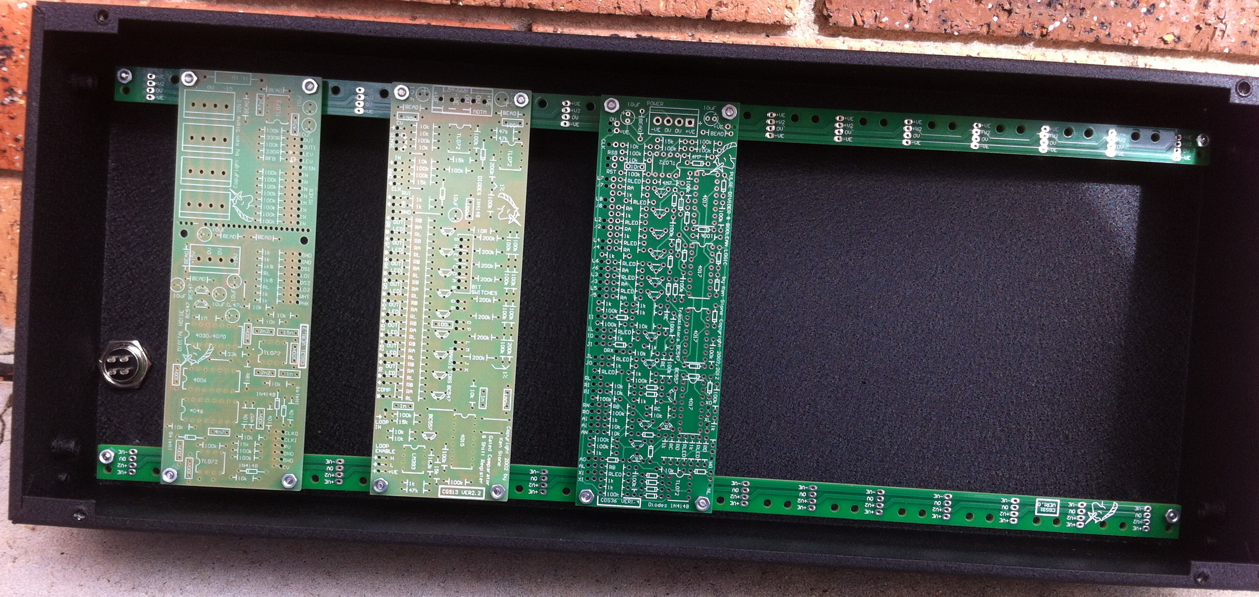
PCB Mounting Rail for Serge style panels.
Pad identification:
ConstructionShort spacers (or a couple of nuts) are needed to space the module boards off the rails so that there is space for the power wire, and so the PCB tracks on the modules are not shorted. 12mm M3 bolts with 5mm spacers is the recommended combination. If using the CGS91 mounted directly to the front panel then the end mounting bolts and spacers need to be long enough to clear your panel mounted components - 16mm bolts with 10mm spacers is the minimum recommended combination. The CGS91 is also suitable for mounting in to the base of the boat and is the recommended approach
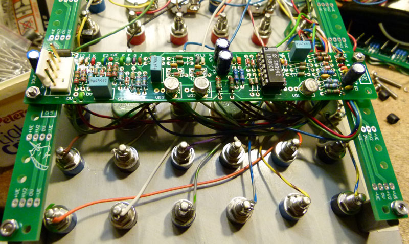
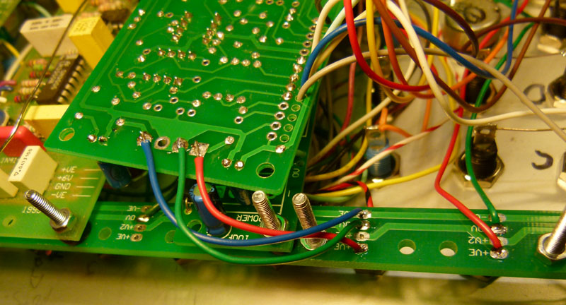
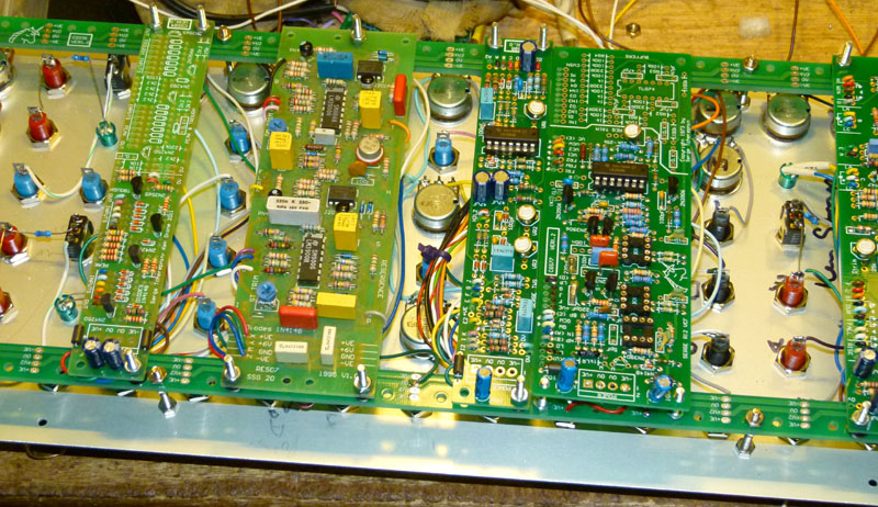
Suggested method for wiring modules to the integral power bus. 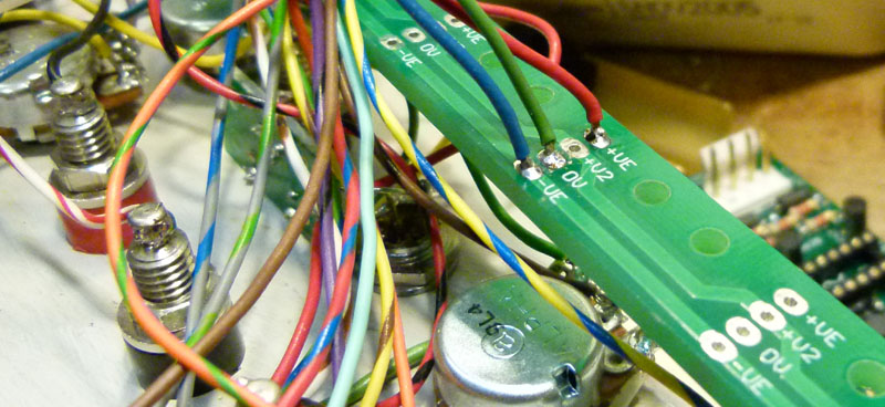
Each module on the panel is connected like this. The other ends of these wires to the rear of a module's onboard power connector. Power can now be fed to the whole panel through that board's power connector. Power connectors could be omitted from all but one PCB on the panel, although if installed, they are convenient for initial testing of the boards off-panel! Parts list
This is a guide only. Parts needed will vary with individual constructor's needs. Article, art & design copyright 2003 by Ken Stone |