|
Reverb UPDATED TO CGS395 This is a basic reverb module constructed around the Belton BTDR-2H Reverb Module. From a single input, two channels of raw reverb are generated. Mix outputs are also provided, allowing the input/reverb mix to be controlled via a panel pot. An additional feedback function is provided for emphasizing the effect, or even for generating screaming feedback. Video demo of prototype unit. A little on how it works:
If you do not require this high pass filter, short out C8. Ken's prototype uses R3=100k, R4=15k, C8=10n(0.01μF). A 20k trimmer in series with R4 allows for gain adjustment. The Belton BTDR-2H Reverb Module comes in three different delay lengths. Select the one that sounds most useful to you. Ken chose one medium delay and one long delay for his prototypes. The 22pF capacitors marked * are to prevent the op-amps from oscillating, however, due to the high value of the feedback resistor, they form a low pass filter. At 22pF, the effect is fairly insignificant. If you have an oscilloscope and can check these outputs, you may try omitting the 22pF capacitors. Construction
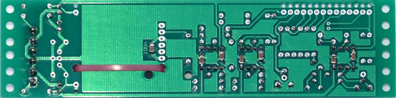
If you are using a 6-pin style MOTM power distribution system with +5 available, you need to install the parts in the area on the PCB marked "A". If you are using the more standard +/-12V or +/-15V two rail systems, you need to install the parts in the area on the PCB marked "B". These parts form a local 5V regulator. Specified maximum current of both the reverb device and the 78L05 device are both 100mA, so if you prefer a larger safety margin, you may prefer to install a 78M05 regulator instead. The unit will run on either +/-12 volts or +/-15 volts. A dual 10k linear pot can be used for the two 10k mix pots. If you do not want the feedback function, simply omit the feedback pot. The FB LEVEL trimmer, 220k resistor and 22n capacitor can also be omitted. 100nF 1206 SMT capacitors are mounted on the rear of the PCB as shown in one of the photos below.
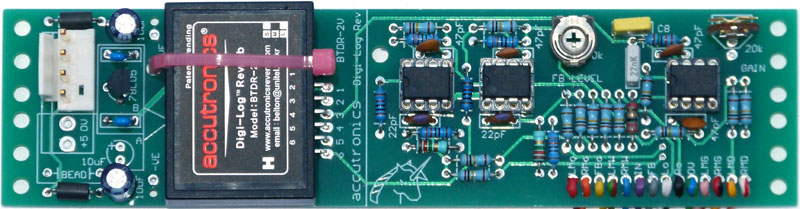
Module assembled for use with external 5V supply
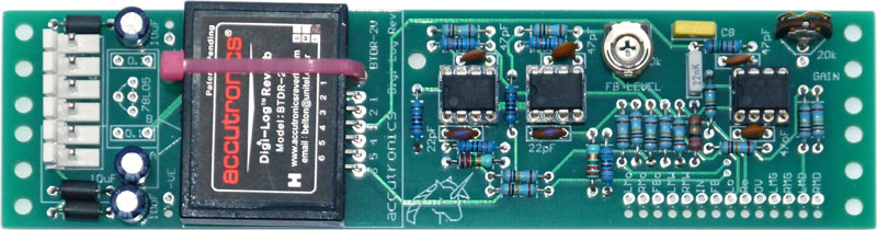
Module assembled for use with internal 5V supply
SMT positions.
Set UpIf you have access to an oscilloscope, you can monitor the input and of one of the "raw" reverb outputs, and adjust the GAIN trimmer so they match. Note that the reverb output will probably have greater excursions than the input signal, especially if you are just using a basic wave shape from a VCO. As such you are setting the level of the "bulk" of the waveform. The alternative method is to adjust the GAIN trimmer until they sound about the same. The feedback trimmer (FB LEVEL) is adjusted with the feedback pot set to maximum. Adjust it to taste. Notes:
Parts list This is a guide only. Parts needed will vary with individual constructor's needs. Article, art & design copyright 2003 by Ken Stone
|