|
Chime Simulator SUPERCEEDED BY CGS419 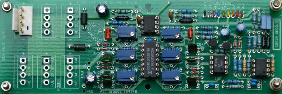
This module contains a pair of two or three tone chimes that are suitable for connection to modular synthesizers. Each chime sound is created by modulating two or three square wave oscillators together, and applying an envelope to the result. Each chime is individually triggered. A simple modulator is used to mix the sounds, resulting in secondary tones that while similar to those generated by a ring modulator, are not as extreme. Two square wave oscillators per chime are quite adequate for producing a good range of tones, though provision had been made to add a third oscillator to each chime. Decay times are adjustable, and if really required, the pitches of the oscillators could be controlled via panel mounted controls, though the PCB is set up to take multi-turn trim-pots. While some frequency settings of the oscillators will give convincing bell or chime sounds, there are many frequency settings that will give discordant sounds. Experiment with it. How to use this module: Connect the inputs to a LFO, a gate sequencer or some other rhythmic pulse source. Connect the outputs to a mixer, or feed them into some relevant part of the synthesizer. Adjust the trim pots (or panel mounted frequency controls) to suitable frequencies. Adjust the decay time to give various bell or chime effects. A little on how it works: Each of the two chimes consists of several distinct blocks, the trigger, the oscillators, the dampers, the envelope generator, the modulator and the buffer amp. We will consider only one channel as both function identically. The trigger (IC1 and associated components) takes any positive going signal that goes over approximately 3 volts and converts it into a narrow positive going pulse. This pulse is fed to the envelope generator, charging the 2u2 capacitor via the diode and 470R resistor. The capacitor is then slowly discharged via the 10k resistor and 100k Decay pot. The result is a positive going percussive envelope. This voltage is buffered by the transistor, which is wired an emitter follower. This voltage is also fed to the inverting input of a comparator (IC2, the damper). When this voltage goes over a minimum preset value, the output of the comparator will go low, enabling all three square wave oscillators. The outputs of these oscillators is crudely ANDed together using diodes an a pull-up resistor. This pull-up resistor is connected to the output of the emitter follower, so the output of the AND gate also has the envelope imposed on it. The result is capacitively coupled to the output buffer. When the envelope has decayed to the minimum preset value mentioned above, the damper again kicks in disabling the oscillators. The purpose of the damper is to stop any signal from the oscillators from leaking to the output when the module is meant to be silent. Construction: 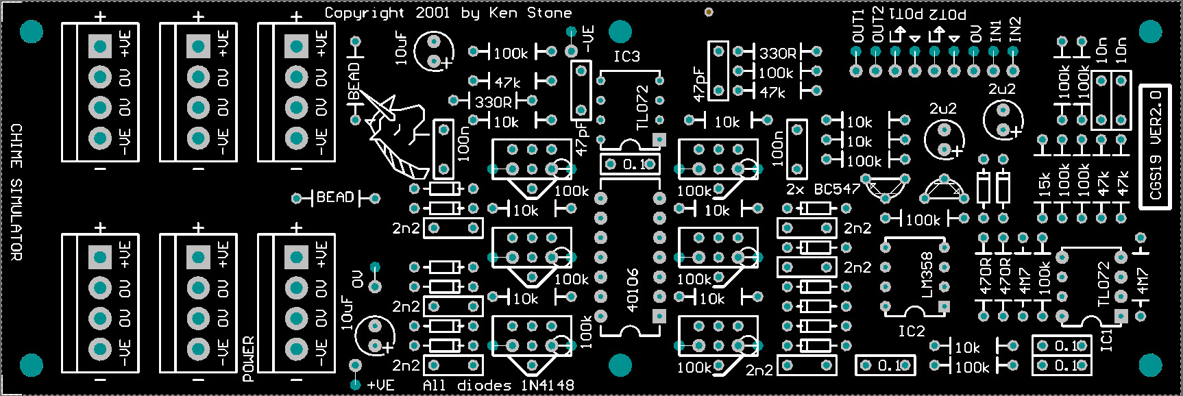
The component overlay. Connections can be determined from the circuit diagram. Setup and Notes:
Parts list This is a guide only. Parts needed will vary with individual constructor's needs. Article, art & design copyright 2001 by Ken Stone |