|
for music synthesizers. The Serge gain cell is a sub-module used in many of Serge's designs, such as the various voltage controlled filters, Quad VCA, mixers, panners and so on. The circuit is proprietary, and I do not have permission to share the schematic. It is sufficient to say that it is essentially a voltage controlled op-amp. It can be used in amplifiers and integrators. Construction 
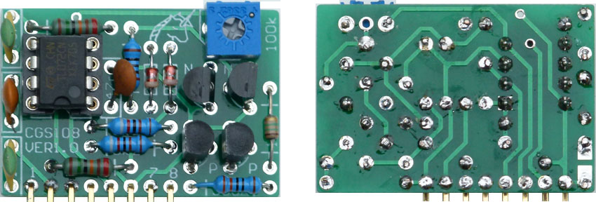
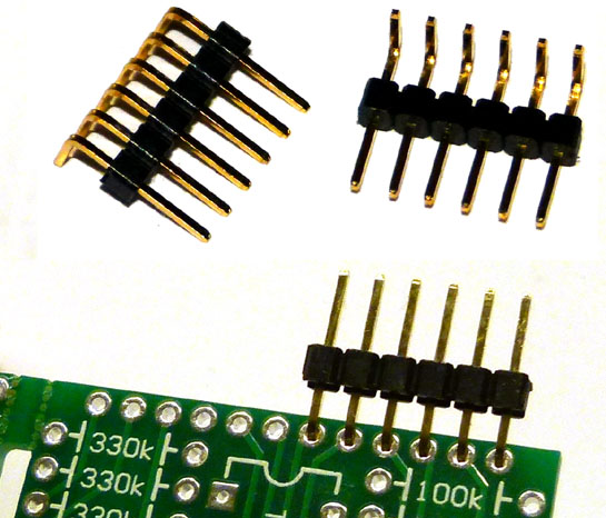
Note that the orientation for the transistors on the overlay is for BC547B and BC557B transistors. The pinout of modern PNXXXX devices is usually the reverse of what was used with the 2NXXXX devices. PN4250 (use instead of BC557B) would need to be installed backwards with respect to the "D" on the overlay. 2N5089 (use instead of BC547B) has variant pinouts depending on manufacturer. Check with the datasheet for the brand you have purchased. Like types of transistors must be matched, more so with the NPN pair, as the trimpot can deal with some degree of mismatch in the PNP pair.. To install the header, slide the pins partially out of the plastic carrier strip so that you can solder the pins as close to the PCB as possible. (Some headers will not need the pins moved.) Before soldering, trim the portion of the pins that go through the PCB so they are just long enough to reach the other side. Once the header is soldered to the PCB, the carrier strip can be carefully clipped off as it is no longer required. Alternatively, the pins could be fashioned from discarded component leads or tinned copper wire of an appropriate gauge. This option will not be as rigid as using a header.
Pad identification
Set Up
To correctly adjust the CGS108, it needs to be wired into the circuit shown above. It can easilly be lashed up on a piece of solderless protoboard/breadboard. A scope is connected to the output. The scope is set to DC, and the beam centered on the screen. Vertical amplification can be set at 2V or 5V per division, and can be adjusted as needed to keep the trace on the screen. A sine wave from an oscillator is fed into the input. The gain pot is NOT connected to the CV input. If the module is working correctly, the input signal will be present on the output. If there is distortion, reduce the level of the input signal. Adjust the trimpot on the module until the peak of the signal below the 0V line on the scope is the same height as the peak of the signal above it. Connect the gain pot is to the CV input. Using it, you should be able to increase and decrease the amplitude of the signal at the output. If you do not have a scope, connect the output to an amplifier. Connect the gain pot to the CV input. Increase the gain until distortion is heard. Use the trimmer on the module to remove the distortion. Increase the gain again, trim out the distortion again, and so on until you reach a point where you can no longer trim out the distortion. Back the gain off slightly and retrim for no distortion. It is possible that the last trimming as described above is the only one required. If using a scope, you may notice some have slightly different overall gain. If so, group the most similar together. These similar ones are best used where better matching will help, such as in the two VCI stages on the CGS112, or the amplifiers in the CGS101. The VCA in the CGS112, for example, does not need to match any other module. Notes:
Parts list This is a guide only. Parts needed will vary with individual constructor's needs.
Article, art & design copyright by Ken Stone
|
|||||||||||||||||||||||||||||||||||||||||||||||||||||||||||||||||||