|
Serge Resonant Equalizer
for music synthesizers.
SUPERSEDED BY CGS522
This module is based on the Serge Resonant Equalizer.
To quote the 1982 catalog:
The RESONANT EQUALIZER (EQ) is a unique ten-band filter designed specifically for electronic sound synthesis and processing. Except for the top and bottom frequency bands, all other bands are spaced at an interval of a major seventh. This non-standard spacing avoids the very common effect of an accentuated resonance in one key, as will be the effect from graphic equalizers with octave or third-octave spacing between bands. Spacing by octaves will reinforce a regular overtone structure for one musical key, thereby producing regularly spaced formants accenting a particular tonality. The Resonant Equalizer's band spacing are much more interesting, producing formant peaks and valleys that are similar to those in acoustic instument sounds.
There are three equalized outputs, two which mix the alternate filter bands, and one which is a mix of all filter bands. The upper (up arrow COMB) lets pass the outputs of frequency bands at 61 Hz, 218 Hz, 777 Hz, 2.8 kHz, and 11 kHz. The lower (down arrow COMB) mixes the other bands (29 Hz, 115 Hz, 411 Hz, 1.5 kHz, 5.2 kHz). This equalizer is different from other equalizers in that the bands can be set to be resonant. When the knobs are in the middle position, the response at the main EQ Output is flat. When the knobs are positioned between the 9 and 3 o'clock position, up to 12 db of boost or cut is set at the band. If
the knob is set beyond the 3 o'clock position, the band will become resonant, simulating the natural resonance of acoustic instrument formant structures. Below the 9 o'clock position, increased band rejection is achieved.
It will work on either +/- 12 volts or +/-15 volts without modification, though in the case of the latter, all input voltage sensitivities, and output voltages are proportionally increased.
A little on how it works:

Click here to view an enlarged copy of the schematic.
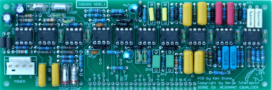
Construction
Pad identification
| A | 61 Hz pot Wiper |
| B | 115 Hz pot Wiper |
| C | 29 Hz pot Wiper |
| D | 411 Hz pot Wiper |
| E | to CW end of all filter pots |
| F | 777 Hz pot Wiper |
| G | lower comb out |
| H | 5.2 kHz pot Wiper |
| I | 1.5 kHz pot Wiper |
| j | to CCW end of all filter pots |
| K | 2.8 kHz pot Wiper |
| L | upper Comb out |
| M | input (to wiper of level pot) |
| N | 11 kHz pot Wiper |
| P | output |
| u | 218 Hz pot Wiper |
| X | +VE in |
| W | 0V in |
| Z | -VE in |
| 0V | 0V/GND connection for 3.5 or 6.5mm jacks and CCW end of level pot. |
|
Example wiring for the Resonant Equalizer.
This diagram still shows the earlier PCB.
While pad positions are different, the markings and connections remain the same. |
Set Up
There is no setup required.
Notes:
- Original Serge kit instructions.
- The module will work on +/-12 volts or +/-15 volts.
- Current consumption of the prototype running on +/-12 volts was 43 mA on each rail.
- PCB info: 6" x 2" with 3mm mounting holes 0.15" in from the edges.
Parts list
This is a guide only. Parts needed will vary with individual constructor's needs. Alternative part numbers are provided in brackets ().
Article, art & design copyright 2003 by Ken Stone
|