|
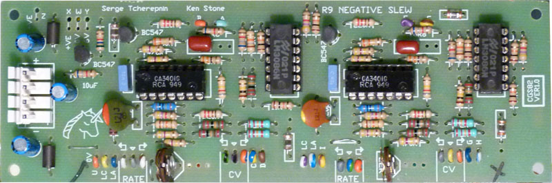
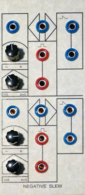
for music synthesizers. This module is a variation on the 1973 Classic Serge Negative Slew module. It is a forerunner to the popular Dual Universal Slope Generator. It is presented here for those who want to build themselves a classic Serge. There are two Negative Slew modules on the PCB. It can be used as both a falling slew rate controller, or a downwards sloping ramp LFO by hooking the pulse out into the input. From a 1970s catalog: The DUAL NEGATIVE SLEW (NEG) is one of the unique multi-functional patch-programmable modules in the Serge system. The module features two independent sections with wide range voltage controllable slew rates. The slew is active in the negative direction only and can be patched to perform a number of synthesizer functions. With the Pulse output applied to the input, the module will regenerate for use as a voltage controlled sawtooth oscillator or pulse generator. An audio signal applied to the input will be envelope detected, and the complex envelope will be available at the output. If a pulse is applied to the input, the unit will function as an envelope generator with a fast rise time and a voltage controlled fall time. A little on how it works:
Construction
Any general purpose NPN silicon transistors should work in this circuit. Take care with your connections, as some have reversed pin outs to the BC547. Traditionally, this design uses an additional 6V power rail. While a pad(Y) is provided, there is no need to connect 6 volts to it, as there is a simple transistor regulator on board. If replacing an existing board in a vintage Serge, you may wish to use the existing 6V rail instead of the inboard regulator. The unit will run on either +/-12 volts or +/-15 volts. The "6 volt" rail will rise to about 7.5 volts when running on +/-15 volts. This is not a problem. Just bear it in mind if you need to do any fault finding. There are emitter follower based LED drivers provided. Due to voltage drops in the drivers and the LEDs themselves, they will drop out part way through each cycle.
Set UpEach slew unit has a trimmer that affects the rate. Use it to set the rates to the range you want, or to standardize your center frequency. Notes:
Parts list This is a guide only. Parts needed will vary with individual constructor's needs. Article, art & design copyright by Ken Stone |