|
SUPERSEDED BY CGS592 This module is a variation on the Classic Serge Smooth and Stepped Generator module. It is presented here for those who want to build themselves a classic Serge. There are both the Smooth and Stepped Generator sections, as well as a small unused circuit left over from other applications on the PCB. From the 1982 Serge catalog:The SMOOTH & STEPPED FUNCTION GENERATOR (SSG) is s a complex multi-functional module to provide various slew and sample functions.
The Smooth section will place a positive and negative slew (glide) on a changing input voltage for lag effects, voltage controlled portamento, and non-linear, low frequency filtering. With the CYCLE jack patched to the input, the Unit will oscillate yielding a voltage controlled triangle wave LFO. A high level into the HOLD input will hold the current output level, whether the unit is oscillating or processing an external control voltage. This is identical to a track-and-hold function. The Stepped function can be used as a sample-and-hold with voltage controlled slew rate limiting. Slew rate limiting limits the size of the step at the output. With the step size limited to a small value, if the input is a random voltage, the output is a random voltage also, but it will only vary slightly from step to step, gradually covering the entire range of the input random voltage. No large changes in the output will be allowed. With the Cycle jack patched to the input and a trigger applied to the Sample input, complex staircase waveforms are generated. The COUPLER is an internal comparator comparing the Smooth and the Stepped outputs. This is useful for generating complex control voltages and for patching a random voltage generator. A little on how it works: |
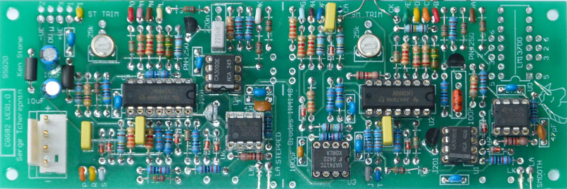
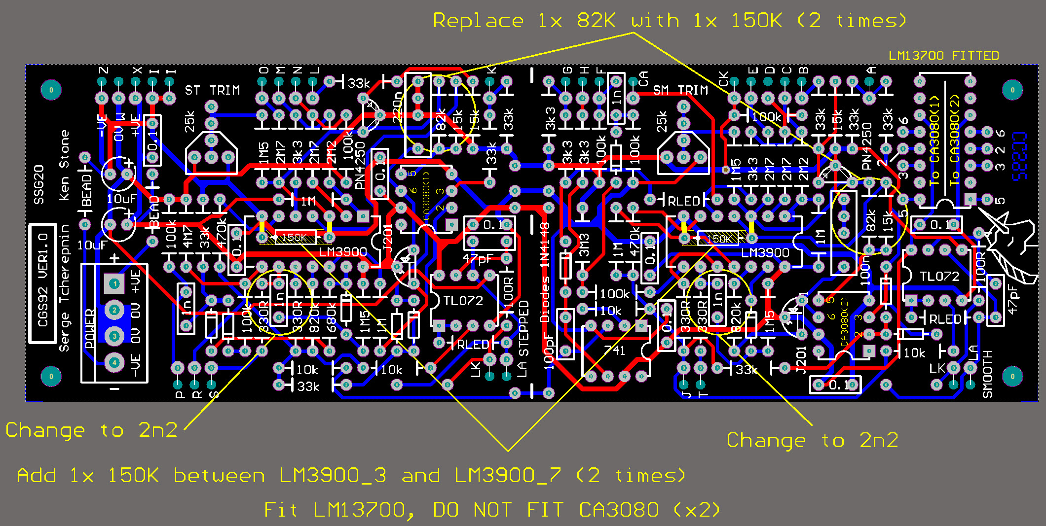
The component overlay for the VER1.0 PCB. Click here for an enlarged, printable version. Print at 300dpi. |
Any general purpose PNP silicon transistors should work in this circuit. Take care with your connections, as some have reversed pin outs to the PN4250. Getting the transistors backwards WILL destroy the chips. Likewise, any general purpose FET should also work.
The unit will run on either +/-12 volts or +/-15 volts.
If you are building this with coloored Banana jacks to the Serge standard, Serge recommends using a non-standard color such as yellow for the coupler (H) and cycle outputs due to their outputs swinging from to near power supply voltages. If you chose to use the G coupler output, a red jack would be appropriate.
Parts used in the circuit between pads F and T can be omitted without affecting the operation of the circuit, although their cost is so small you may as well install them in case you ever wish to experiment with that pulse converter.
Any trimpots between 20k and 100k are suitable for use.
Serge suggests that linear pots between 30k and 50k are suitable for use. Ken's prototype used 100k pots without trouble.
Due to the rarity of the CA3080, Component Kits are being supplied with the LM13700. In this instance the pads marked '2', '3', 5' & '6' should be connected to the associated pads on one CA3080 and repeated for the second set of pins on the second CA3080.
The 2x 82K resistors will also need to be replaced 150K resistors and 2 additional 150K resistors added between pin 3 and pin 7 of each LM3900. In addition, the 1nF capacitor shown should be changed to 2n2 - see overlay.
The first time you power it up, we would suggest you do so with 22 ohm resistors in series with the positive and negative power rails. This should save the chips if you have made a blunder.
| PAD ID | Function |
| A | Smooth input |
| B | Hold input |
| C | Smooth Cycle output (+/- swing close to power supply voltage) |
| D | Smooth VC input |
| E | Smooth Rate pot wiper |
| F | Gate to Trigger converter input (not used) |
| G | Coupler output (approx 0 to 5V swing when powered by +/-15 volts) |
| H | Coupler output (+/- swing close to power supply voltage) |
| I | -VE connection for pots. |
| J | Smooth Output |
| K | Stepped input |
| L | Connects to S pad (Hold input) |
| M | Stepped Cycle output (+/- swing close to power supply voltage) |
| N | Stepped VC input |
| O | Stepped Rate pot wiper |
| P | Stepped Sample input |
| R | Stepped output |
| S | Connects to pad L |
| T | Gate to Trigger converter output (not used) |
| W | 0V power connection |
| X | +12V power connection |
| Z | -12V power connection |
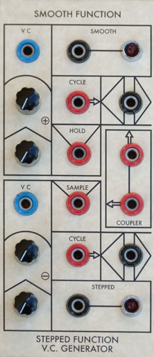
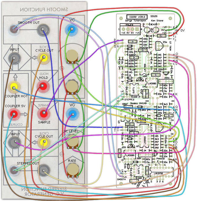
| Example wiring for the Smooth and Stepped Generator. |
Set Up
From Serge kit instructions:
For this module to work properly, a jumper must be installed between pad S and pad L. (This should have been installed during construction, although if you wish to test the two parts of the Stepped generator individually, it can be left disconnected until you have.)
Patch the CYCLE output of the Smooth Function into the IN jack. Monitor the OUTPUT while turning the RATE knob full clockwise. The pitch should be about 100 Hz, and should go to sub-audio rates (as seen from the LED'S) when the knob is turned down. Check that a control voltage into the VC IN jack will control the rate. Note that this is an attenuating input only, with no inverting processing.A high level applied to the HOLD input (greater than about 4.5 volts) should stop the Smooth Function from cycling. With the Smooth Function patched to cycle, connect the CYCLE of the Smooth Function into the SAMPLE input of the Stepped Function. Patch the Stepped Function CYCLE to its IN jack. Using the STEPPED OUT to control the pitch of an oscillator, listen for the pitch change motion as the Stepped RATE is turned up. When fully clockwise, a triangular "staircase" waveform will be generated by the Stepped Function Generator. For best audible rate, the Smooth Function should be fairly slow. As the Stepped RATE knob is turned down, the staircase will slow down.
Notes:
- The module will work on +/-12 volts or +/-15 volts.
- PCB info: 6" x 2" with 3mm mounting holes 0.15" in from the edges.
Parts list
This is a guide only. Parts needed will vary with individual constructor's needs.
Article, art & design copyright by Ken Stone