|
The Triple Comparator consists of three independent functions which are useful in the production of square waves and variable pulse waves. The Comparator reference level can be a time-varying control voltage, a complex audio signal, or a fixed preset voltage. Additionally, the comparators are useful for level detection and for logic decisions based on amplitude. The module also contains a single, non-adjustable, Schmitt trigger.When running from +12 volts, the output of the Schmitt trigger will rise to about 5 volts when the input falls below approximately 0.6 volts and will fall to approximately 0 volts when the input rises over approximately 4.3 volts. This section of the module is frequently left off panels It will work on either +/- 12 volts, or +/-15 volts. No negative power rail is used. A little on how it works:
The schematic for the Triple Comparator Construction
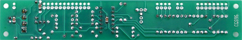
Note: On the VER1.0 PCB, do not use the 0V pad. Instead use either the CCW end pad of the pots or the spare pad at the edge of the PCB next to R3 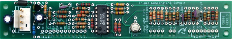
The lower photograph shows the position sof the three 100mF SMT capacitors
Set up: Connect a bipolar triangle wave (i.e. AC coupled, or having equal swing above and below 0V) into the B input. Set the top (B) pot fully counterclockwise. Adjust the trimmer for a 50% dutycycle output. Use a scope, if you have one, or set the speed of the triangle wave low enough that you can use the LED to monitor the outputNotes:
Parts list
This is a guide only. Parts needed will vary with individual constructor's needs. Article, art & design copyright by Ken Stone |