|

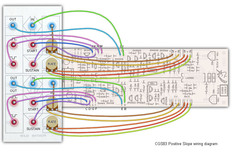
for music synthesizers. This module is a variation on the 1973 Classic Serge Positive Slew module. It is a forerunner to the popular Dual Universal Slope Generator. It is presented here for those who want to build themselves a classic Serge. There are two Positive Slew modules on the PCB. It can be used as both a rising slew rate controller, or a upwards sloping ramp LFO by hooking the lower pulse out into the Start input. In this configuration it also operates as a utility oscillator, suitable for fixed key sequencing and general sound effects and noise making. It is not suitable for tracking a keyboard. A little on how it works: Sending a gate or trigger into the START jack will cause the slew generator to lock into a rising waveform, regardless of what is happening at the other inputs, although the ramp is affected by them. The upper PULSE OUT remains on for this period. When the peak of the cycle is reached, both the OUTPUT and upper PULSE OUT outputs reset. Sending a gate into the SUSTAIN jack will will start a cycle, much like above, with one difference. Once the cycle ends, and fore as long as the gate signal remains, the OUTPUT with remain at its peak, and upper PULSE OUT will remain on. The lower PULSE OUT is derived from the analog OUTPUT. It is NOT an inverted version of the upper PULSE OUT. Connecting this output to START or SUSTAIN will cause the Positive Slew to operate as a VCO or LFO. The VC input has a processor style level pot, allowing the response to the incoming control voltage to be tailored to respond directly to the signal, or to respond to it in reverse. If not running a cycle as described above, the OUTPUT will follow any signal at the input, with any rising voltage subject to slewing as set by the RATE pot and any control voltage present at the VC input.

Construction
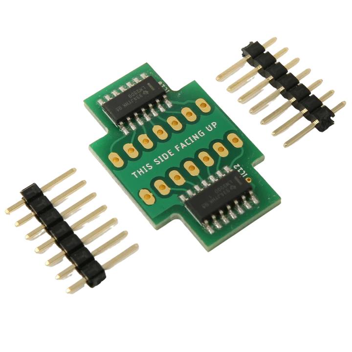
Any general purpose silicon transistors should work in this circuit. Take care with your connections, as some have reversed pin outs to those shown on the overlay. Traditionally, this design uses an additional 6V power rail. While a pad(Y) is provided, there is no need to connect 6 volts to it, as there is a simple transistor regulator on board. If replacing an existing board in a vintage Serge, you may wish to use the existing 6V rail instead of the onboard regulator. The unit will run on either +/-12 volts or +/-15 volts. The "6 volt" rail will rise to about 7.5 volts when running on +/-15 volts. This is not a problem. Just bear it in mind if you need to do any fault finding. There are no LED drivers provided. If you wish to add LEDs, use some of the modern high brightness LEDs. Connect their cathodes to 0V. Connect their anodes to the corresponding output jacks via 4k7 resistors. There are two 22k resistors used as pulldowns on the sustains input. Using 100k resistors here will bring this input up to modern standards. 100k linear pots can be used for all pots, despite what is written on the diagrams. Likewise, the trimmers can be any value between 20k and 100k. Some builders are having an issue with the 2 sections interferign with each other. We recommend trying this modification from Prism Circuits which uses a small PCB to provide a seperate LM3900 for each section
You will need to remove the existing IC Socket and replace it either with two 1x7pin Receptacles or you can solder the kit direct to the PCB ensuring that it stands clear of any surrounding components.
Set UpEach slew unit has a trimmer that affects the rate. Use it to set the rates to the range you want, or to standardize your center frequency. Notes:
Parts list This is a guide only. Parts needed will vary with individual constructor's needs. Article, art & design copyright by Ken Stone |