Click for larger image |
potentiometer + resistor(s) = modified potentiometer
Before proceeding with this article readers are advised to ensure that they read the last paragraph of this article with regards to applying any of these ideas to an actual circuit.
Most potentiometers are supposed to have a fairly straightforward linear or logarithmic characteristic. This is all right in most applications but sometimes the particular characteristic required is not readily available. Fortunately, it is not difficult to obtain various modified characteristics by adding one or two fixed resistors. Which is what this article is about.
The indications `lin’ or `log’ on a potentiometer refer to the intended effect of moving the wiper along the track. The resistance measured between the wiper and one end of the pot is supposed to increase in linear or logarithmic fashion as the wiper is moved along the track. This type of characteristic is usually drawn in a graph, where the resistance between the wiper and the end of the track is expressed as a percentage of the total resistance, and plotted as a function of the wiper position.
There are applications where the characteristic is unimportant. Not many, though. In most cases, the type of adjustment required dictates the `ideal’ pot characteristic for that application. The next step is to find out whether it exists.
The three most common characteristics are shown in Figure 1. The wiper position (for either a rotary or slider pot) is plotted along the horizontal axis as a percentage of the total track length: x = 0 corresponds to the `low’ end (fully anti-clockwise for a rotary pot) and x = 100 stands for the other extreme position.
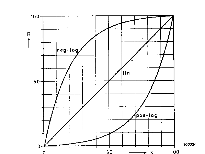
Figure 1. Three types of pot are normally available: those with linear,
logarithmic (`pos-log’) and anti-logarithmic (`neg-log’) characteristics.
The vertical axis gives the percentage resistance between the wiper and the `low’ end of the track.
The `linear’ characteristic is the easiest one to draw: it goes in a straight line from zero resistance at the low end to maximum resistance at the other.
Pots marked `log’ are supposed to have a so-called positive logarithmic characteristic; this is the one marked `pos-log’ in Figure 1. In this case, the attenuation in dBs varies linearly as a function of the wiper position
Finally, a less well-known characteristic is the `anti-log’ pot (`neg-log’) in Figure 1. As can be seen, it is a mirror image of the normal logarithmic plot.
|
So much for the theoretical characteristics. What about real-life pots?
Well…. Figures 2 and 3 give the results for a whole series of logarithmic and linear pots, respectively. The linear pots are bad enough, but the log versions are hopeless!!!. |
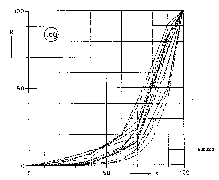
Figure 2. In practise, so-called logarithmic pots may have a wide variety of characteristics. In practice, the desired characteristic is approximated more or less by a series of straight lines. |
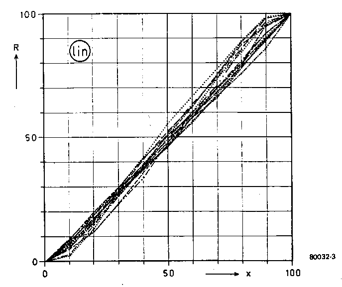
Figure 3. Linear pots are usually better. The main problems occur at the two extreme ends |
|
Add a resistor or two…
Fixed resistors can be added between either or both ends of the pot and the wiper as shown in Figure 4.
The result is still, basically, a pot – but its characteristic can be weird or wonderful, depending upon the ratio between the total pot resistance and that of the fixed resistor(s).
|
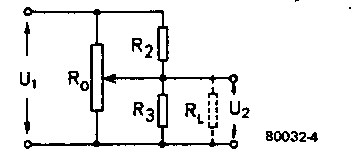
Figure 4. One or two fixed resistors can be added,
Between the wiper and one or both of the ends.
The results can be surprising! |
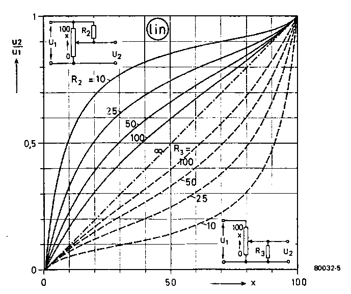
Figure 5. These characteristics can be obtained by Adding one resistor to a linear pot.
|
The possibilities are plotted in a fascinating array of graphs. Figure 5, for example, shows what can be achieved by adding one fixed resistor to a linear pot.
The pot resistance is taken as 100 `units’; the fixed resistor value can then be given as a percentage. `R = 25’, say, means that the value of the fixed resistor is 25% of that of the pot – a 470K pot and a 120K fixed resistor is a close approximation.
In Figure 5, the full lines in the upper left-hand half correspond to the situation where the fixed resistor is mounted between the top of the pot and the wiper; the dotted lines show what can happen if the resistor is mounted in the position for R3.
|
Note that two plots for R = 10 (i.e. one-tenth of the total pot resistance) are fairly close approximations of the anti-log and log characteristics. This means that a 4K7 linear pot can be modified to a 4K7 log by adding a 470R resistor between the wiper and the `low’ end!. For what it’s worth, the theoretical results of `padding’ a log pot with one resistor is given in Figure 6. The upper plot for R2=10 is a reasonable approximation of a linear characteristic.
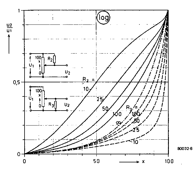
Figure 6. Provided one has access to a log pot with a theoretically ideal characteristic,
These modified characteristics can be obtained by adding one fixed resistor.
|
What about adding two resistors?. Why not. The results (see figure 7 and 8 for lin and log pots, respectively) are intriguing, to say the least. In these plots, one resistor is taken as 25% of the full pot value and the plots are given for various values of the other: the circuits given in the top left and bottom right-hand corners correspond to the full and dotted line plots, respectively.
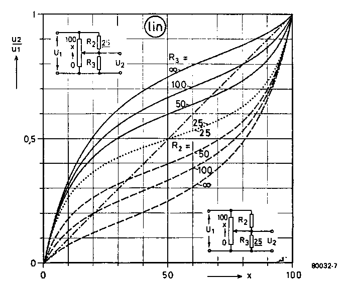
Figure 7. Using two resistors and a linear pot. The full lines correspond to the situation where R2 is fixed, and equal to ¼ of the total pot value; the dotted lines are obtained when R3 is fixed and R2 is varied. |
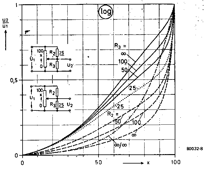
Figure 8. A logarithmic pot and two resistors can produce this intriguing set of plots. As before, the full lines are valid when R2 is fixed and R3 is varied and the dotted lines are obtained when R3 isfixed at ¼ of the total pot value. The basic logarithmic plot is also indicated, as a reference. |
Finally, Figures 9 and 10 give some idea of what can be achieved if the two resistors have the same value, varying from 10% to 100% of the total pot value. Obviously, all these plots must run through the point where the wiper is set to half the total resistance value. Anybody who wants fine control in the centre of the pot range and coarse control toward the ends should take a look at the plot for R2 = R3 - 10 in Figure 9.
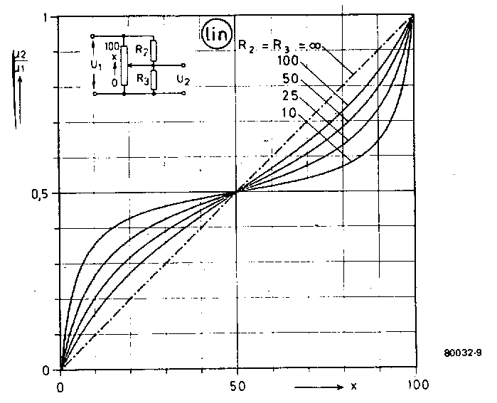
Figure 9. Using a linear pot and two equal resistors. This set of plots can be obtained. |
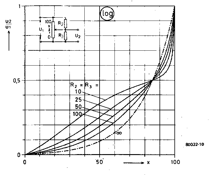
Figure 10. Similarly, two equal resistors can be used in combination with a log pot. |
'Add a resistor or two’ we said. And look what happened!.
Two more things can happen, not so obvious from the plots. The total resistance of the modified pot is no longer constant, or it is reduced. The circuit driving it may not like this… Also, the plots given for fixed resistors between the wiper and the `low’ end of the pot may be taken as dire warning… The same sort of thing will happen if a relatively high-value pot is followed by a relatively low-impedance circuit!.
From an article written by G. Reinhold for Elektor December 1979.
|


