To replace the CV/GATE it is proposed that a separate 'data bus' be defined. Being separated from the power buss opens up the possibility for a larger number of CV/GATE signals to be supported - essential for a multi-voice or multi-phonic system - as well as allowing a greater flexibility in where the 'data bus' goes. There are 3 signal types that need to be considered:-
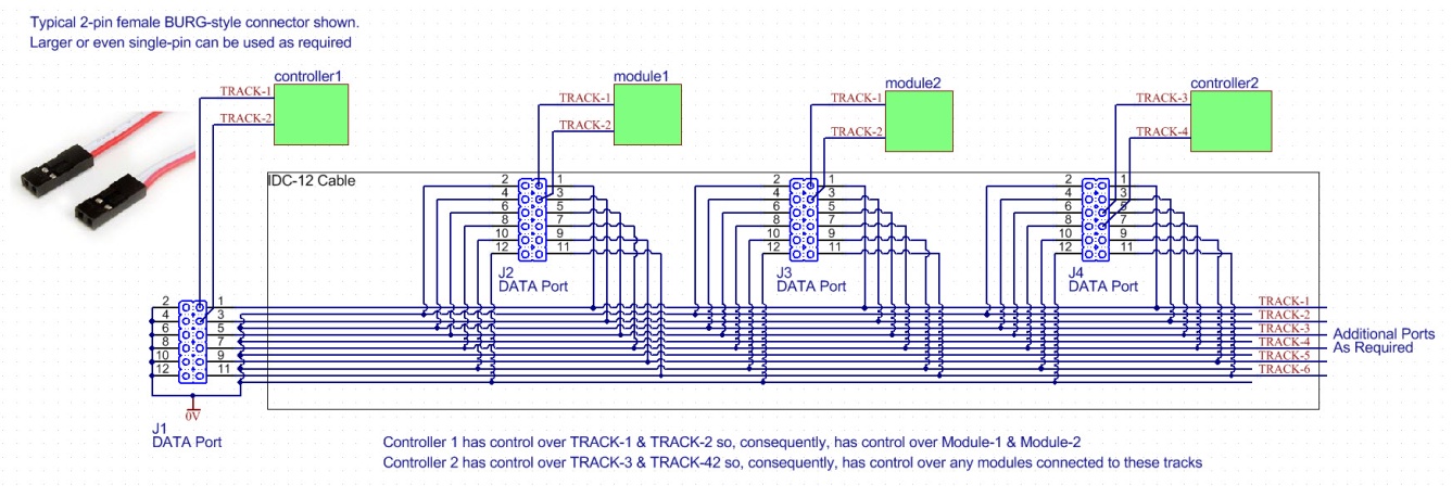
CV/analogue: GATE/logic: While CV/GATE lines can, generally, be integrated in to a single bus/connector, it is proposed that a separate dedicated communication bus be implemented. The CV/GATE Connector: A suitable connector must be low-cost and easy to terminate. EuroSynth proposes using a 12-pin IDC connector and cable with pin assignment as show below: The example connector shown here provides 8x 'tracks' each with an associated 0V wire or 'ground path'. A system can comprise multiple DATA Ports allowing systems to be divided in to zones and/or to allow a 'controller' to communicate with an almost limitless number of devices. The IDC connector is well established in the EuroRack world and so requires no new specialist tools or knowledge. At the module end a 2-pin 0.1" MTA-style header would be used to access a pair of Tracks which would for example, typically replace the original CV/GATE. The connecting cable between the module and the DATA Port would be a 2-wire cable terminated with a 2-pin header at both ends. At the DATA Port end the header is fitted to the header by plugging in to a pair of 'odd pins' eg 1 & 3, 5 & 7. In noisy environments, screened leads may be terminated to the appropriate 'even pins'.
It should go without saying that a mechanism will need to be employed to allow the user to determine what signals are what, where they are going to and where they are coming from. In a multi-DATA BUS system it will be very easy to lose 'track' of a signal. The Communication Network: The MIDI protocol is a well established and recognised communication protocol not only in the EuroRack market but in other fields such as lighting. As such, it is proposed that the Communication Network be a MIDI-based network. As this network will, generally, be confined within the users system, it is feasible to utilize a 2-wire bus that will allow both reading and writing of data between devices. The choice of for the physical media is open to conjecture but following the IDC path adopted with the power distribution, it is proposed that a 6-wire IDC arrangement be used with the following pin assignments:-
It is then a trivial matter to add more nodes to the bus should extra points be needed. To allow the network to be connected across multiple systems, the ‘external interface, should revert to the standard MIDI current-loop medium, allowing for longer inter-system distances and improve noise immunity. This would also allow for the use of standard MIDI cables for system interconnect. The external interface connector can be either the regular 5-pin DIN connector or a 3.5mm TRS which is becoming a regular ‘mini’ alternative. The external interface would be an ‘intelligent interface’ and would include MIDI MERGE functionality to allow ‘conventional’ MIDI equipment to also be connected. Devices within the users system such as MIDI-CV Converters or MIDI Sequencers could then connect to the network rather than require to be externally patched. |


© Copyright 2000. All rights reserved. Revised: September 20, 2022