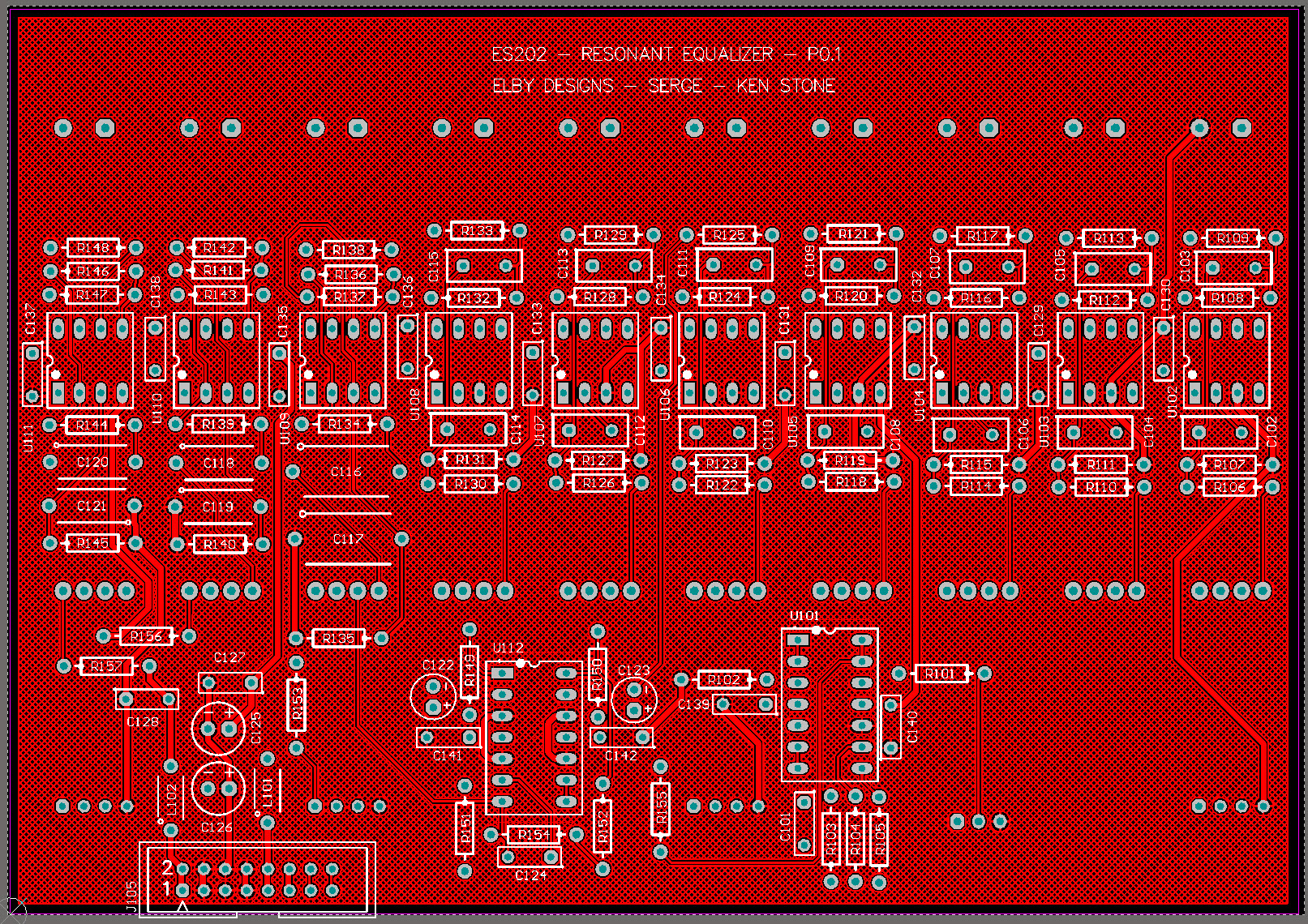
Constructors should refer to the Component Overlays along with, Before starting assembly, please read the ‘Slider Installation’ notes at the end of this document.
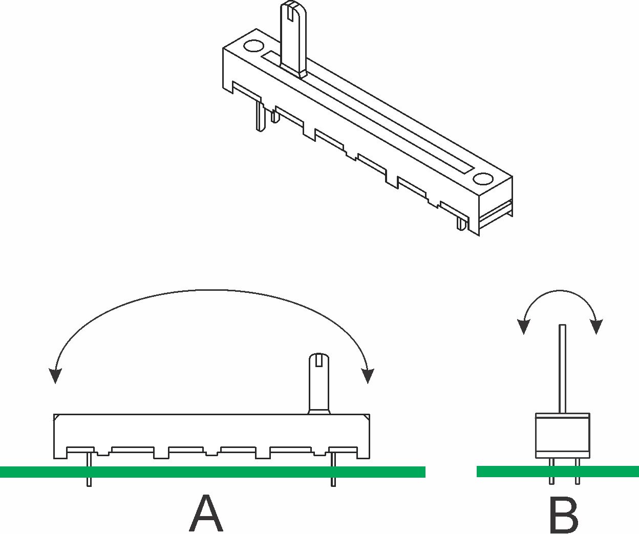
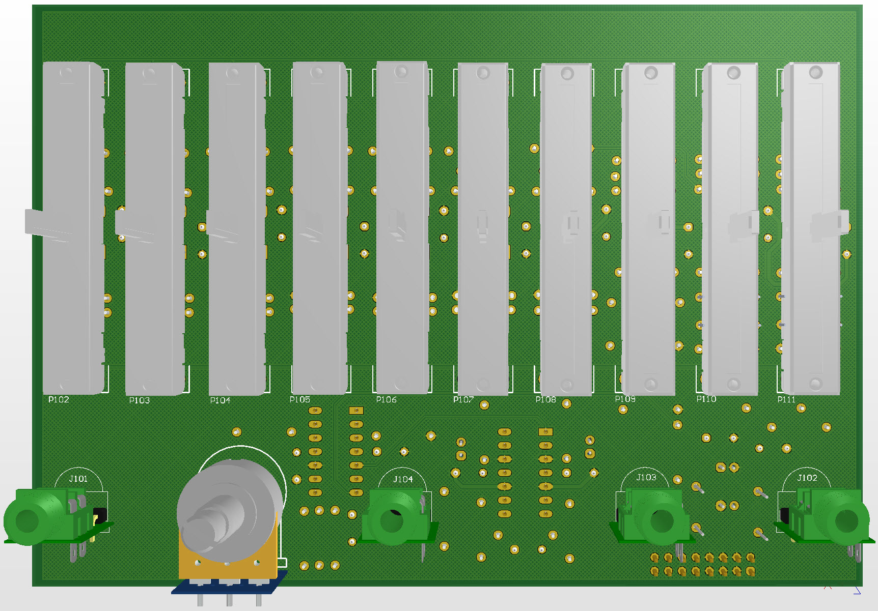
Slider Installation Although the main component installation on to the main PCB is straightforward, installation of the sliders is trickier and requires a bit of manual dexterity and patience. The sliders need to be square to the pcb in both the ‘A’ plane and the ‘B’ plane.
Errors in the ‘A’ alignment will result in the slider being higher at one end that the other. This will not affect the operation of the slider but may look cosmetically ‘untidy’ if all the sliders have varying tils in different directions. Errors in the ‘B’ alignment will not affect the electrical operation of the slider but may cause the slider shafts to rub against the slots in the panel resulting in poor slide action. Although the sliders have support pins, these cannot be used in this assembly due to the fact that we have exposed solder pads for components mounted on the underside of the pcb in the region of the sliders. In the current assembly instructions we utilise the fact that when the assembly is inverted i.e. front face of the panel facing down, that the sliders will rest against the back of the front panel and so should, naturally sit square to the pcb. An alternative approach that users may wish to try is to utilise some of these components as spacers themselves. There are 2 resistors under each slider than could be mounted on the same side of the pcb as the sliders. If mounted firmly and squarely to the pcb then the sliders can ‘sit’ on these resistors. It should be possible to tack a slider leg at each end with the pcb in its normal orientation and to then finish full soldering without going through the fiddly process of aligning of the sliders. The resistors to use in this approach are:- Top row - R109, R113, R117, R121, R125, R129, R133, R138, R142, R148
|
||||||||
|
No Calibration Needed |


© Copyright 2000. All rights reserved. Revised: November 8, 2023