|
3D Model |
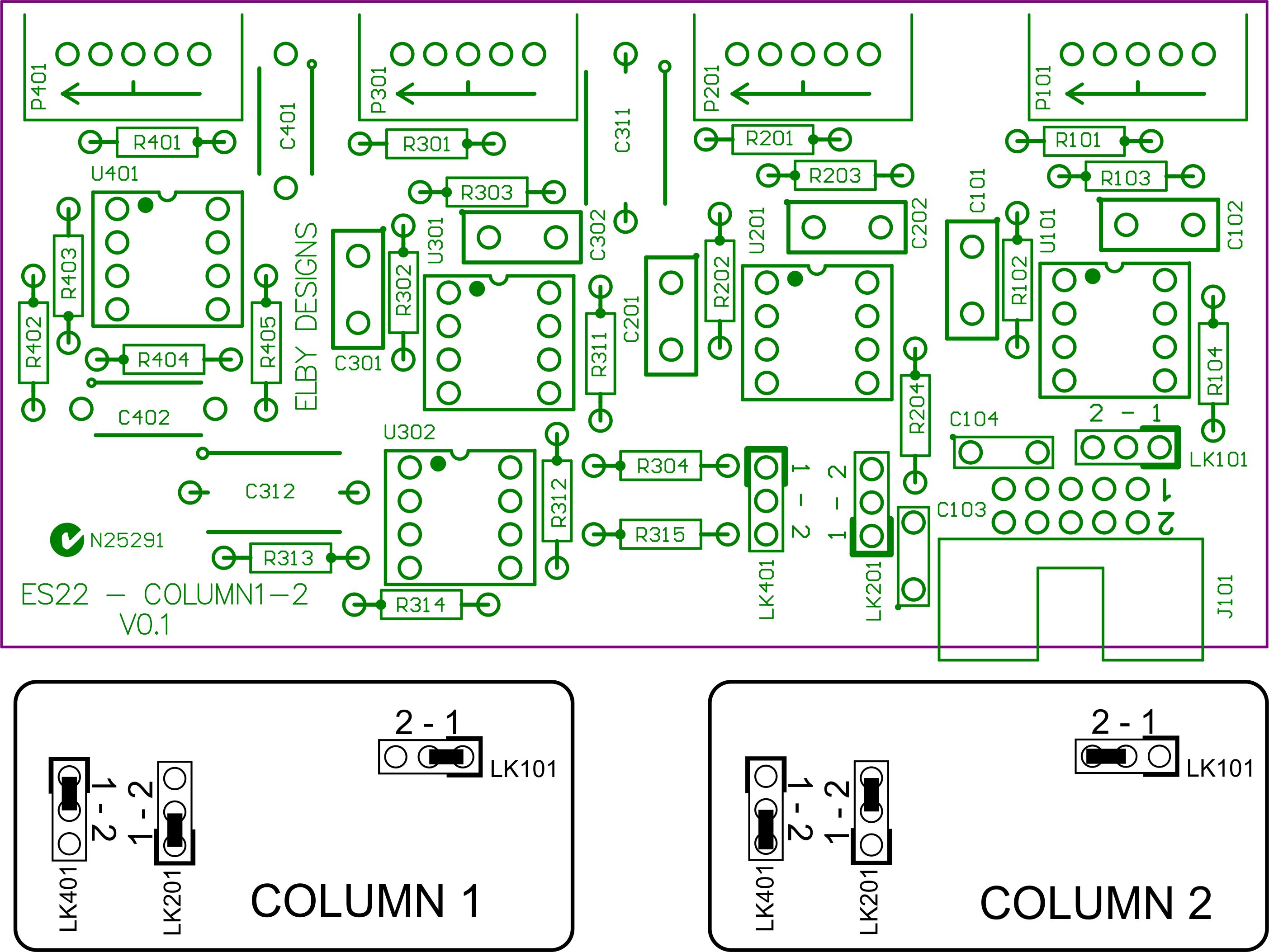
Overlay |
Plan View |
Column 1 PCB |
|
|
|
Column 2 PCB |
|
|
|
Column 3 PCB |
|
|
|
Constructors should refer to the Component Overlays along with,
the Bill of Materials for the current value of all components, and
the General Construction Notes for general PCB assembly guidelines.
Refer to this drawing for installation of the links on the Column 1-2 PCB.
Addendum
- Mount R405 vertically in the left pads of R405/R407
- Mount R407 vertically in the right pads of R405/R407
After fitting J502 on the Column 3 PCB you need to add 2 short wire links as shown on the overlay :-
- 1 link on the underside from J502_1 to the bottom leg of R204, and
- 1 link on the underside from J502_3 to the right leg of R304.
The Column 3 PCB has been factory modified for this modification.

