|
What are in the Kits we supply?
For our 4U family we supply PCB's, Component Kits and Hardware Kits as individual items. This allows the buyer flexibility in the parts they want so, for example, they can buy just the PCB and then supply the components and hardware from their own sources, or they could buy the PCB and Component Kits to get the main section of the design built to a know level of compliance with the design and then source their own hardware so that the finished product fits a style they want.
We do not have front Panels for the individual modules in the 4U family but do have 'system panels' that combine several modules to perform a desired 'system function'.
For our 3U family we supply Full Kits, which includes everything needed to build the design i.e. comprises PCB(s), Component Kit and Hardware Kit.
We can supply PCBs and Front Panels for our 3U family, just email us with your request.
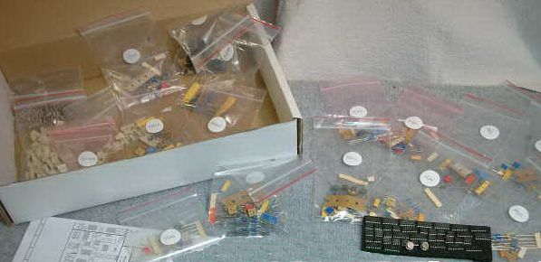
| Component Kits |
contain all PCB components required to dress the relevant
PCB.
They do NOT contain the PCB(s) or panel components such as pots, sockets,
switches or LEDs |
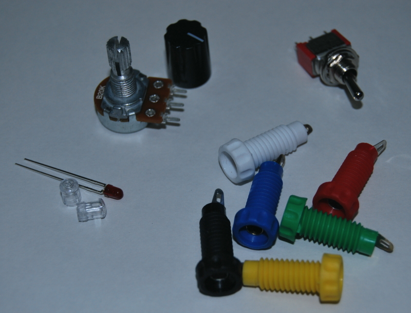
| Hardware Kits |
contain
all panel components including pots, switches, knobs and and LEDs
|
| Full Kits (3U) |
contain all PCBs, Front Panels, the Component Kit and the Hardware Kit |
| Full Kits (4U) |
contains PCBs, Front Panel, Component Kits and Hardware Kits for all the modules in the 'system', Front Panel, Boat and in addition includes Mounting Kits for all the PCB assemblies and other miscellaneous parts to complete the build of a fully functional 'boat' |
We strongly recommend the use of our Component Kits as the parts supplied have been selected to provide optimum compliance of the finished build with the original product design. This also means that we are able to supply components that fit the PCB footprints, have the desired specification (or better) that the design requires and hence ensure its operational compliance with the design specification.
General
specifications of items contained in our kits are as follows:-
-
- All pots are Alpha 16mm, 0.5W with
6mm, 18-tooth splines
-
All capacitors less than
1nF are generally NPO/Low K Ceramic Disc or 2.5% Polystyrene
-
All capacitors between 1nF
and 1uF are generally Polyester
-
All capacitors greater than
1uF are generally 25V Electrolytics or 35V Tantalum
-
All
ICs are high-grade components
-
IC sockets have machined pin inserts
Where can I find the Build Guide for my kit?
The Build Guide for a product can be found by either:-
- clicking on the 'Datasheet and Build Guide' link at the bottom of the product page in the shop, or
- clicking on the 'WebTek - Datasheet and Build Guide' category at the left of the shop and navigating through the WebTek site
Basic 'how to use' instructions can be found here
Can I get schematics/PCB artwork for the modules?
Schematics are provided for some of our kits.
PCB and Panel artwork is not available for any of our products.
For other projects schematics may not be provided due to licensing agreements or IP protection I will also add this quote from a respected designer when asked about modifying one of their designs.....
WHY CAN’T YOU ACCEPT IT FOR WHAT IT IS?
Why all the modifications, are we really improving the instruments, or is your ego giving you bad advice?
You own the instrument, modify it if you please. But perhaps pause a minute and consider the extraordinary amount of work that has already been put into the instrument. Perhaps you should just enjoy that first, before you get out the power drill.
Take a deep breath, grok any synth in its fullness, use your creativity to tackle its limitations to inspire you or change your direction.
Are your projects hard to make?
This one is tricky to answer. It all depends on your ability.
We now classify our kits as CCK (Competent Constructor Kits) not DIY and we would list the following as basic requirements for anyone attempting build any of our kits: |
 |
- Be able to read resistor colour codes
- Be able to determine and/or identify other components such as transistors, diodes and semiconductors
- Be aware of component polarity
- Be able to read a Bill Of Materials (BOM) and know how to apply it when building a kit
- Be able to solder reasonably well
- Have the patience to read through all the user documentation
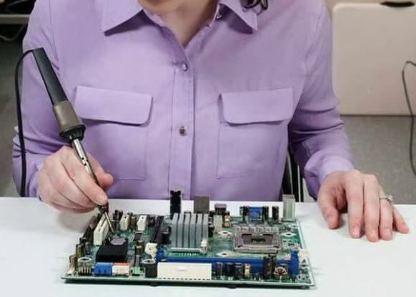
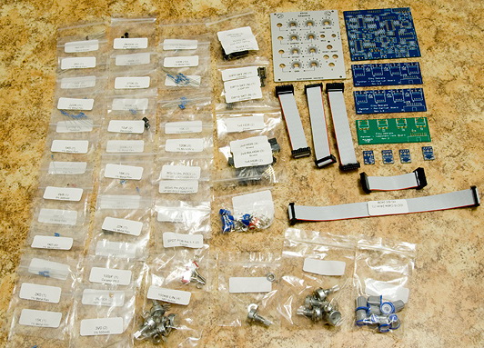
- Know how to properly use tools (see image above!)
- Be able to use a multimeter and, ideally, an oscilloscope and have access to these tools. Some of these tools are needed for calibrating the completed build. Most of them are needed for simple fault analysis.
- Be able to read a circuit diagram (where these are available)
|
 |
If you can't tick ALL of these boxes then we would suggest that these kits are not suitable for you.
If you want to get started, perhaps, a good way is to start on something simple like a small hobby kit from your local electronics store. Have a dabble, build up your confidence and basic skills then go for it. But please note that we cannot accept responsibility for the performance/operation of your finished products as we have no control over the way the kits are built. If you have problems it is inevitably due to an assembly error and you should read the next section on how to rectify the problem(s).
My project doesn't work, what then?
Join one of the many forums such as Mod Wiggler.
Then after checking that your question hasn't been answered you can post to the list for advice.
If you still can't get the completed and undamaged module going, you can send it back to ELBY Designs to fix.
You will have to pay for postage both ways, any parts required and our labour time at AUD$50 per hour with a minimum service charge of AUD$25.
You must first pre-arrange with us in regards the return as we have limited time and will need to ensure that we can provide this service to you in a mutually acceptable time period.
Please note that we will not support projects where the user has opted to modify the design including (but not limited to) - (a) changing component values or (b) making alterations to parts of the circuit - as detailed in our Bill Of Materials and Build Guides.
Are all your boards lead-free?
All boards are RoHS compliant, which means they do not contain lead.
All boards can be soldered with either lead free solder or lead based solder.
What sort of solder should I use?
All of our boards can be soldered with either lead free or leaded solder.
We still prefer to use Pb/Sn solder for our own in-house projects because it is easier to work with.
If using active-resin based solders be sure to clean the boards afterwards with a proprietary PCB cleaner to remove all traces of resin. You do NOT need to clean 'no-wash' or 'no clean' solders, some may leave a white deposit which is harmless.
What modules do I need to buy to make a modular synthesiser?
Everyone will have their own preferences so its difficult to recommend specific modules for a complete system. The various synth forums are a good place to find 'getting you started' advice.
Can I get just PCBs and/or Front Panel?
We do not supply Front Panels for the CGS boards. The CGS forum is a good starting point to see if there are any group buys or surplus sales of other users panel designs. We can create a panel design for you and would use the Front Panel Express design tool and their associated service. Contact us by email if you wish to get a design made.
Panther Front Panels are available by email request.
Panther PCB(s) are available by email request. These are the full set of PCB's used in the project and may include some of our Panther Support boards. If you are building the project to fit a different housing and/or front panel design you may find some of these boards superfluous.
How deep are your Panther EuroRack modules?
When quoted, the module depth is the distance from the inside face of the front panel to the most extreme outside edge of the module. This depth includes an allowance for a fitted IDC Power Cable.
Most of our modules now use a plug-in main board that sits parallel to the front panel and for these modules the standard depth is 60mm (standard module) but a few modules still need to use a perpendicular configuration and are inevitably (but not always) a little deeper (deeper module).
Module widths are in units of HP where 1HP = 5.08mm (0.2"). We do not restrict our panel widths to multiples of 2HP. This allows us to provide an optimum panel layout without compromising panel space or cramming panel components together.
General Module Information
Please read this document for general installation notes and guidance
The information given relates specifically to our Panther famiy of modules but can, in general, be applied to other products offered.
Products are designed to run from a regulated dual-rail power supply of +/-12VDC. A power supply system up to +/-15VDC can be used without damaging the modules although the module may require some minor component value changes to optimise output levels. Protection circuitry is not included and so it is the responsibility of the user to ensure the correct termination of the product to its power supply.
Products are cooled only by natural convection so it is important to allow adequate space around the product to ensure unobstructed air flow.
Standard precautions should be taken when installing products as for all electronic instruments.Do not place ona source of direct heat, in direct sunlight, or near other instruments that may result in intereference with either's operation.
Products are usually equipped with brushed aluminium panels and should be treated with according respect. These panels can be cleaned with a soft, barely, damp cloth.
(*) The 0V power supply is connected to the front panel and should be grounded for safety. The ground reference should be provided via a chassis terminal to a suitable mains-earth point. The user should note that introducing multiple grounding points may lead to ground-loops and it is the responsibility of the user to ensure that those problems are treated in a competent and legally correct manner.
Products use good quality 3.5mm (1/8"), 4mm (banana) and 6.35mm (1/4") connectors. Users are advised to use plugs that meet the basic specification detailed in the attached drawings. Cheaper plugs can have shorter tips, shorter body lengths or even differently shaped tips and may not may proper contact with the socket points or not properly active the break contacts (which are used in some applications to provide normalised connections).
We use polarised power connectors for most of our products. It is the responsibility of the user to ensure that connecting cables are fully compliant with this (i.e. they are mechanically and electrically correct) and that mating connections on 3rd-party products are compatible.
When installing a product in to its case, make sure all internal cables are properly folded so as not to get pinched or come in to contact with hot surfaces.
(*) Connecting to external equipment (such as a mixer or amplifier)
When connecting an output (or input) from a module socket to an external piece of equipment it is essential that there is a common '0V Reference' between the 2 pieces of equipment. In the past this has been 'sloppily' provided with the patch lead by virtue that the screen/shield connection of the plug/lead connects to '0V' points in both systems. This is a bad method for several reasons which are beyond the scope of this article. You should always establish that a proper, dedicated '0V Reference' connection is in place. This will usually involve a dedicated cable that is connected to the 0V rail of both systems. In your modular, this should (ideally) be taken from a terminal nearest to the main power supply input to your system. On the external equipment there may already be a GROUND/EARTH terminal provided for this purpose or you may need to have one fitted. If you experience hum problems or tingling through static discharge, then you probably don't have a solid, reliable '0V Reference' NB: THat static discharge is usually as a result of improper chassis grounding.
Statutory Information
ELBY Design EuroSynth products are designed in accordance with the Australian Communications and Media Authority (ACMA) regulatory compliance requirements.
Where applicable, products will carry our RCM mark. |
 |
I want to design my own modules. Where can I get basic technical information?
| ELBY Designs has adopted the EuroSynth Specification which was initially derived from the Doepfer A100 Technical Specification |
 |
|