Build Guide - Installation

Power is connected to J701.

MIDI Interceptor requires a supply of, typically, between 12VDC and 15VDC. The supply should be able to deliver up to around 250mA.

The 0V and 5V needed for the panel wiring are available from P102_3 and D101_1 connectors as shown. This connector should NOT be connected to an external 5VDC, it is a power OUTPUT not a power INPUT.

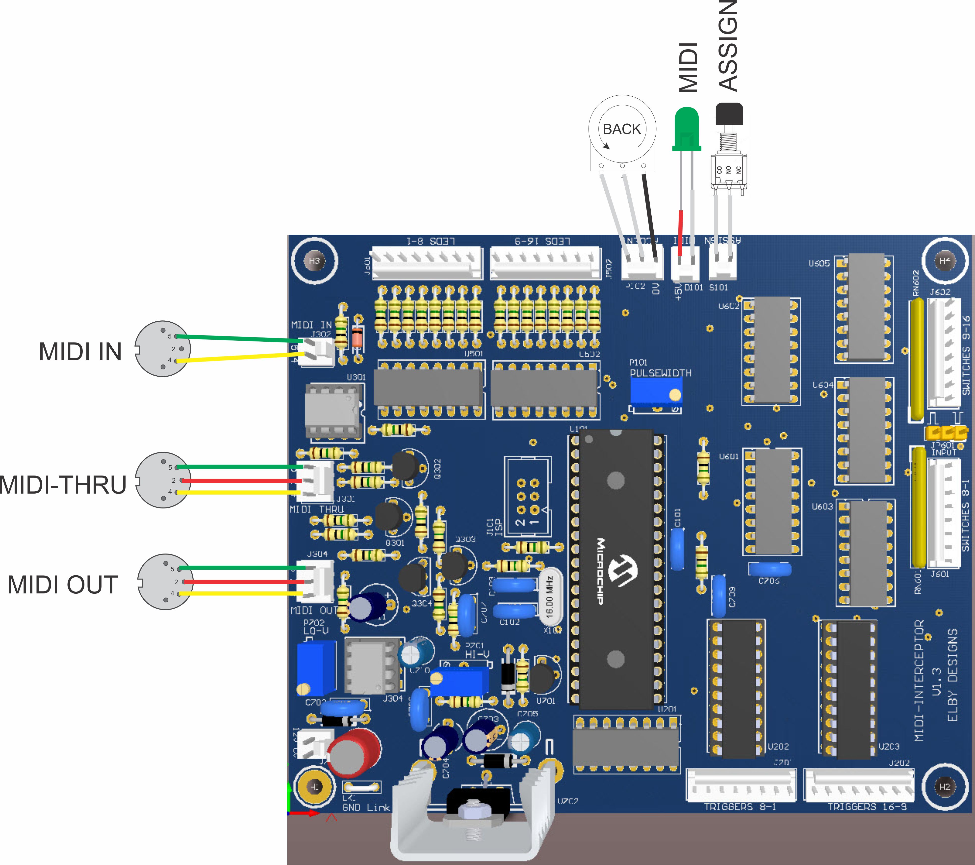
MIDI connections are made to J301, J302 and J304.

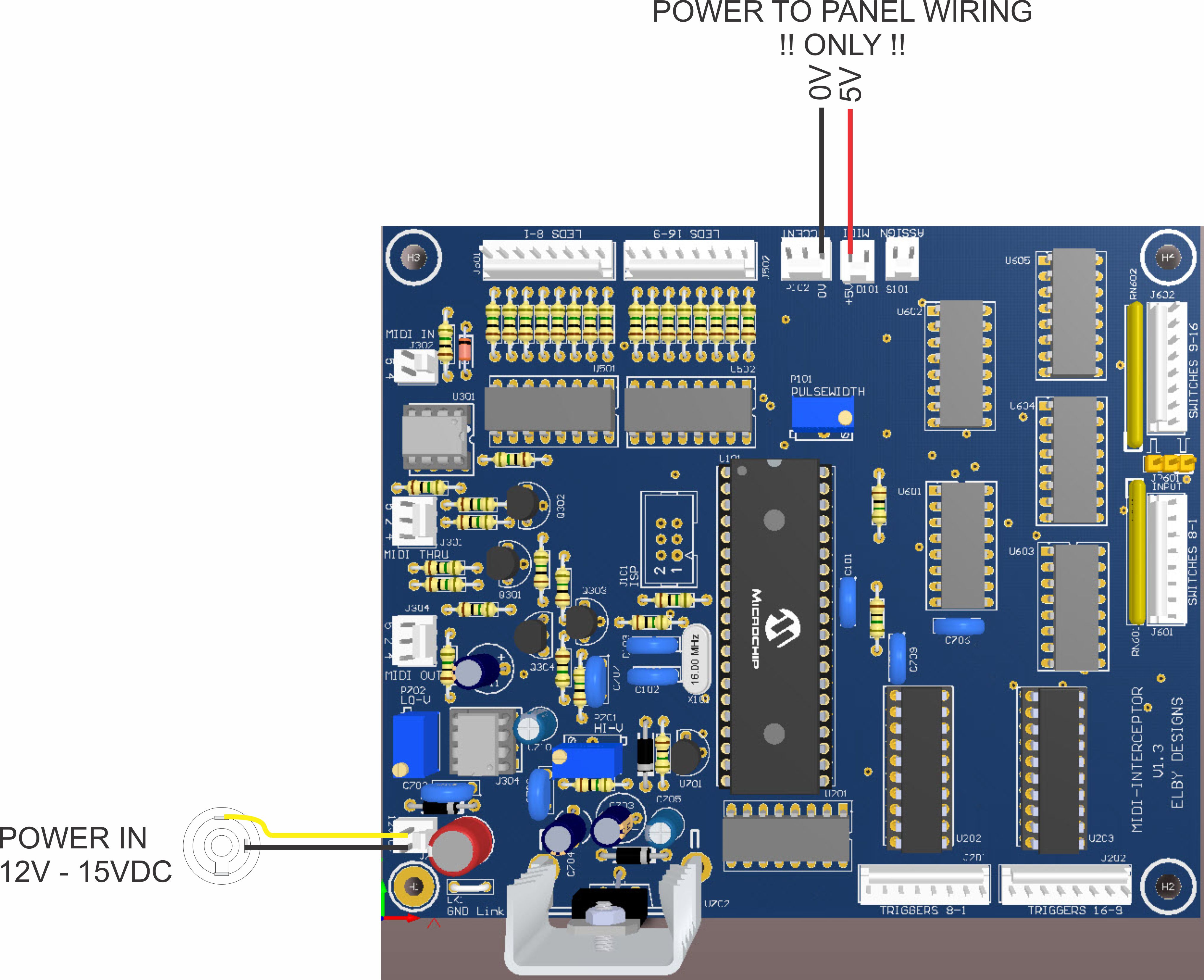
A MIDI LED can be connected to D101 and indicates the receipt of valid MIDI messages.

An ASSIGN switch can be connected to S101. This should be a normally-open switch with momentary-action such as a pushbutton switch.

The ACCENT pot is connected to P102 and should be in the range of 20K to 100K with a linear action. If a panel control is not required then a small trimpot should be

  • wired to the connector and located in a secure place if using a pre-assembled MIDI Interceptor, or
  • soldered on to the PCB in place of the header P102.

LEDs for status indication of the trigger channels are connected to J801 and J802. If using a multi-digit LED display device then they must be configured for a common-anode connection which is connected to the units +5V supply.

It is desirable to use low-current LED's to minimise loading on the supply. The MIDI Interceptor has onboard current-limiting resistors which set a current loading of ~2mA per LED.

Incoming trigger signals for your systems 'controller' are connected to J601 and J602. These signals should be 5V logic and must be referenced to the units 0V power rail.

JP601 should be set to reflect the logic mode of these inputs.

Trigger outputs are available at J201 and J202. These are positive-voltage outputs referenced to the units 0V power rail.
Email:  elby-designs@bigpond.com
© Copyright 2000. All rights reserved.     Revised: November 30, 2022