|
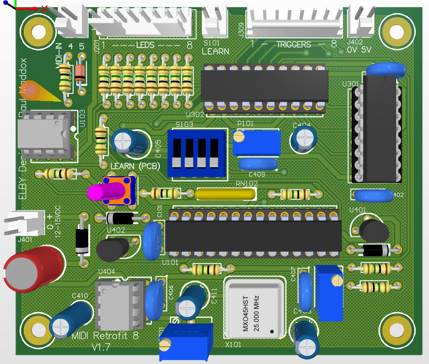
3D Model |
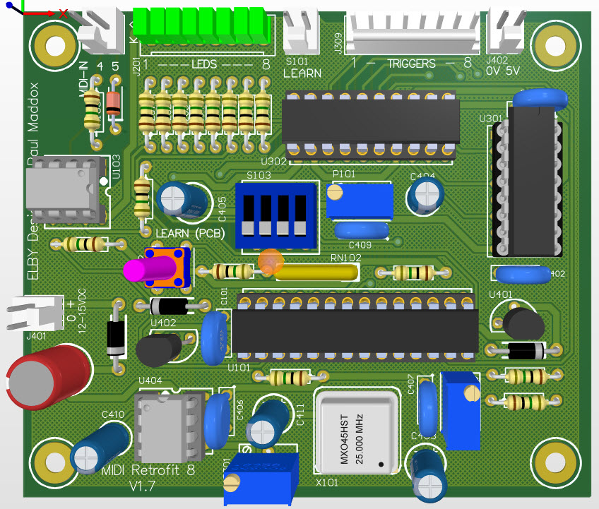
Overlay |
Plan View |
|
|
|
|
Constructors should refer to the Component Overlays along with,
the Bill of Materials for the current value of all components, and
the General Construction Notes for general PCB assembly guidelines.
Construction of the MIDI-Retrofit-8 is pretty straight forward. Attention must be paid, as usual, to the orientation of polarized components and the usual ESD procedures should be in place when handling sensitive components.
Construction should follow these simple steps:-
- Dress the MIDI-Retrofit-8 PCB with all components as required – see Build Options
- Mount C102 across the terminals of S101 on the underside of the PCB
- Install the board using the four mounting points
- Install all required panel components
- Connect panel components to the board using equipment wiring and the supplied crimp terminals
Build Options
There are a couple of build options that will be dependent on how you will be installing the MIDI-Retrofit-8 and will affect the selection of some components on the PCB.
LED Indicators
The LED Indicators serve 2 functions:
1. The LEDs flash whenever their respective TRIGGER Output is fired and so allow the user to observe the ‘trigger pattern’
2. The LEDs provide a ‘progress indication’ during the [LEARN] mode
If you intend to re-assign the TRIGGER Channels on a regular basis and/or wish to have a visual status indcator of the TRIGGER status then we recommend that the LEDs be fitted external to the PCB in an easily viewable location along with the [LEARN] switch.
Install the 8-way MTA header as shown at right.
An external momentary pushbutton switch should also be connected to S101.
|
|
If you intend to re-assign the TRIGGER Channels only once or rarely, and don't require a visual indication of the TRIGGER status then mounting the LEDs on the PCB is recommended.
Install 8x LEDs as shown at right.
The external [LEARN] switch is then not normally needed as the internal switch is provided for that purpose.
|
|
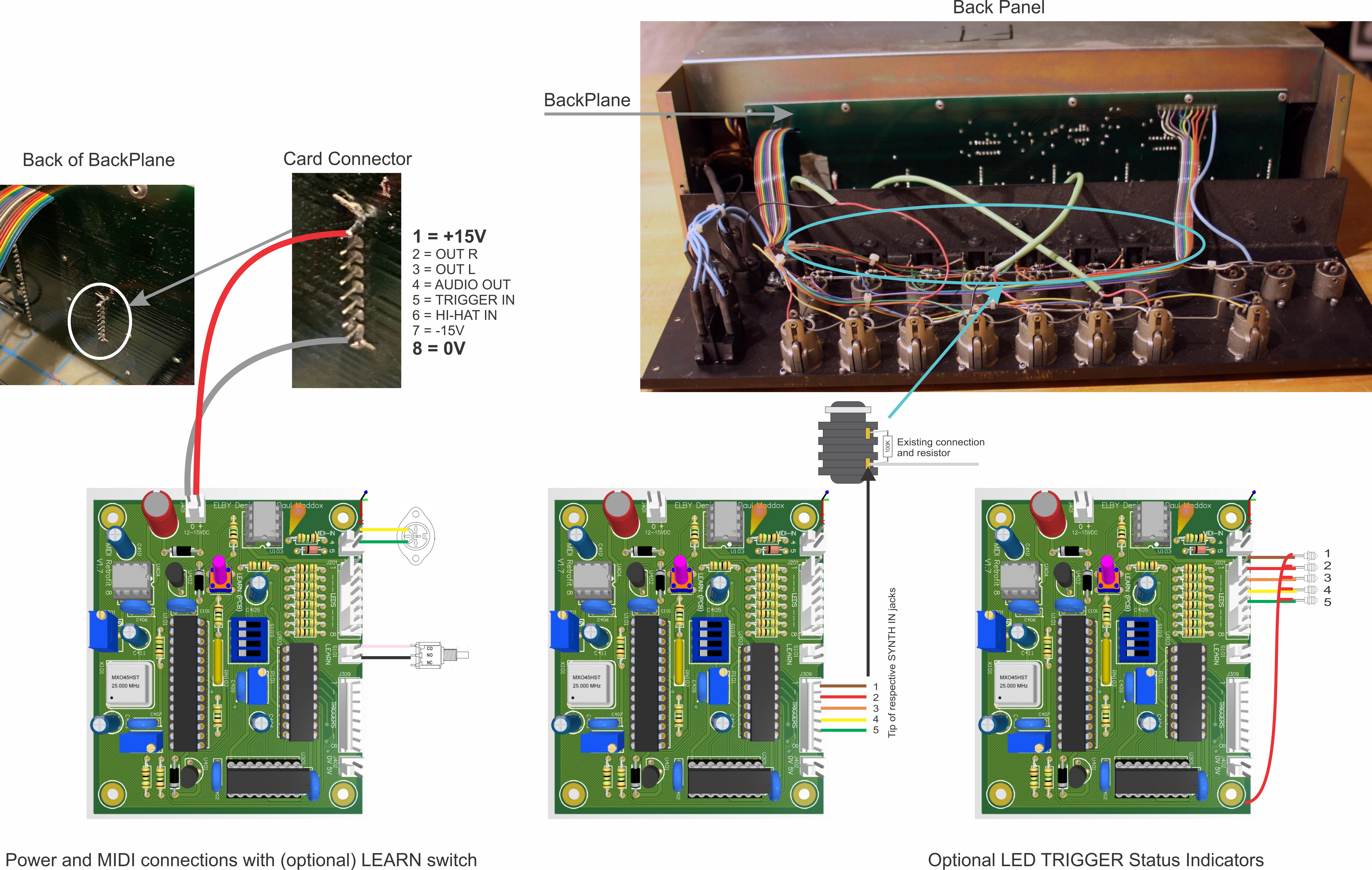
J402 is used to provide:-
- 0V to the external TRIGGER jacks (not required if the PCB is installed inside the unit being controlled), and
- 5V to the LED anodes (if external LEDs are fitted).
This should not be used as a 5V power supply for external equipment
and you must NOT connect this to an external 5V supply.
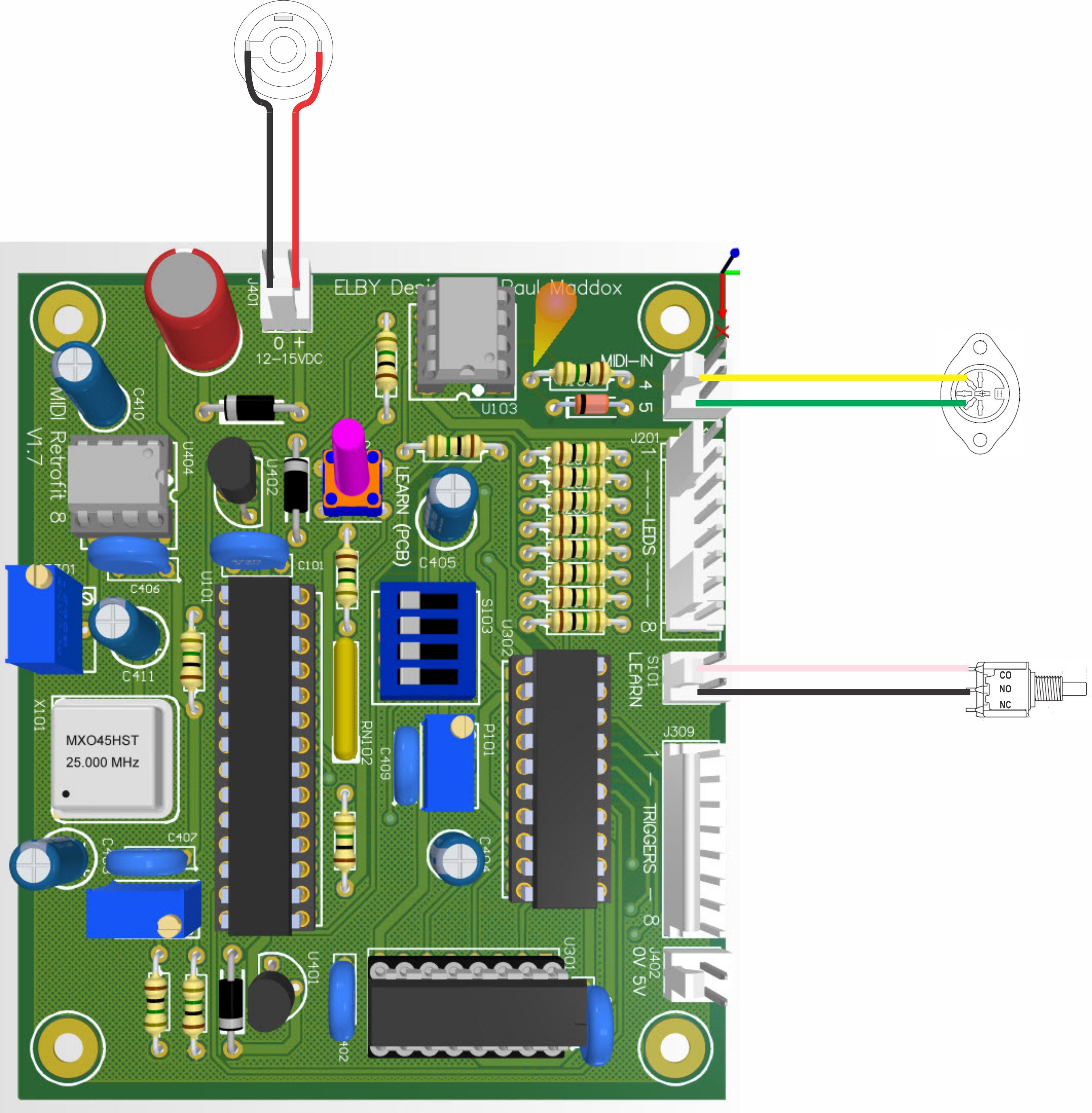
J401 is the power connection for the MIDI-Retrofit-8. The supply should, ideally, be in the range of 12VDC to 15VDC which is normally derived from the equipment itself.
J101 is the MIDI IN connector, connect it to J101 as shown at right.
If an external [LEARN] switch is being installed, connect it to S101 as shown at right. |
|
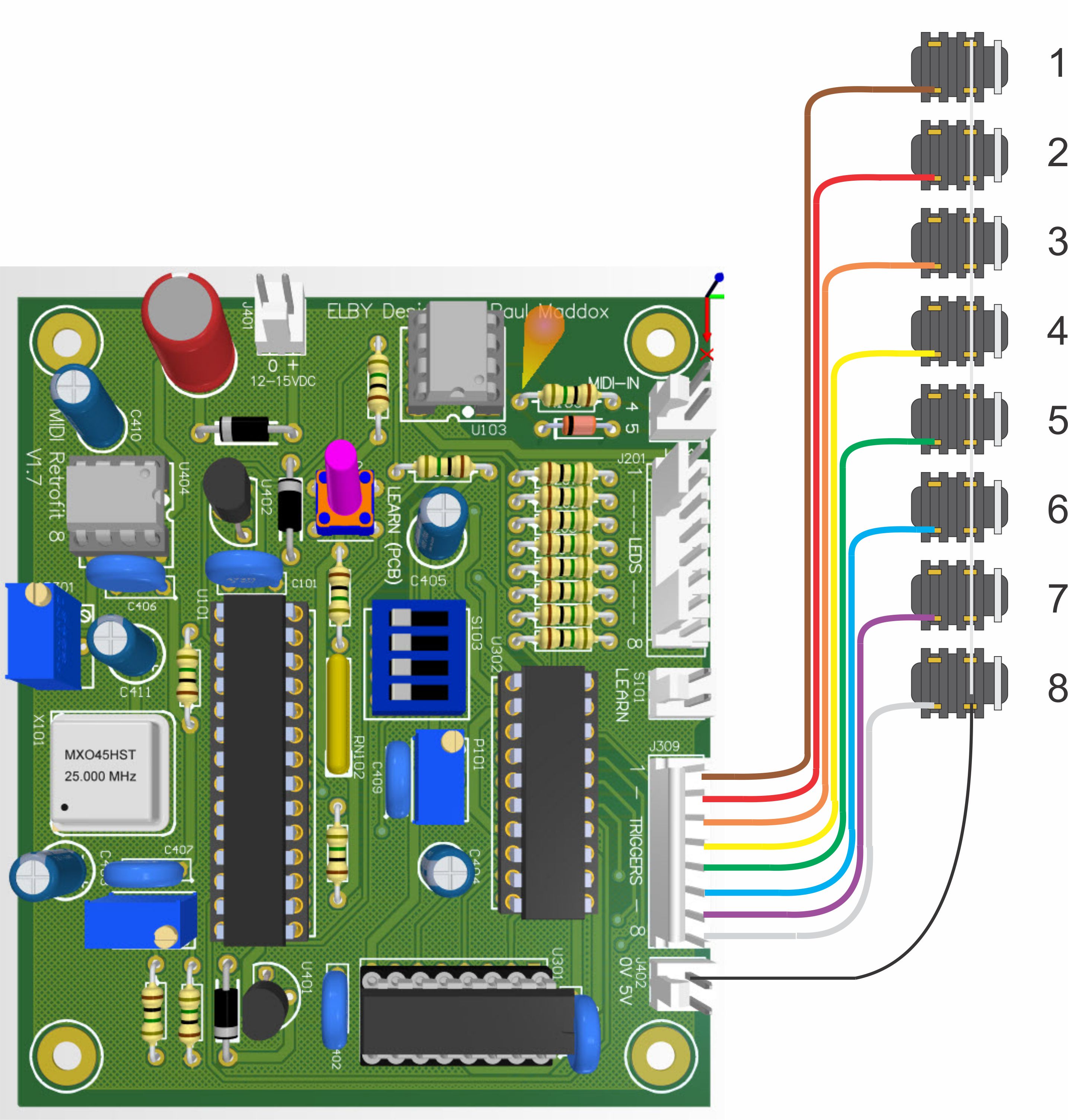
When installing external TRIGGER Output jacks, terminate their ‘signal’ contacts to J309 as shown at right. Common the SCREEN/SHIELD terminals to J402_1.
|
|
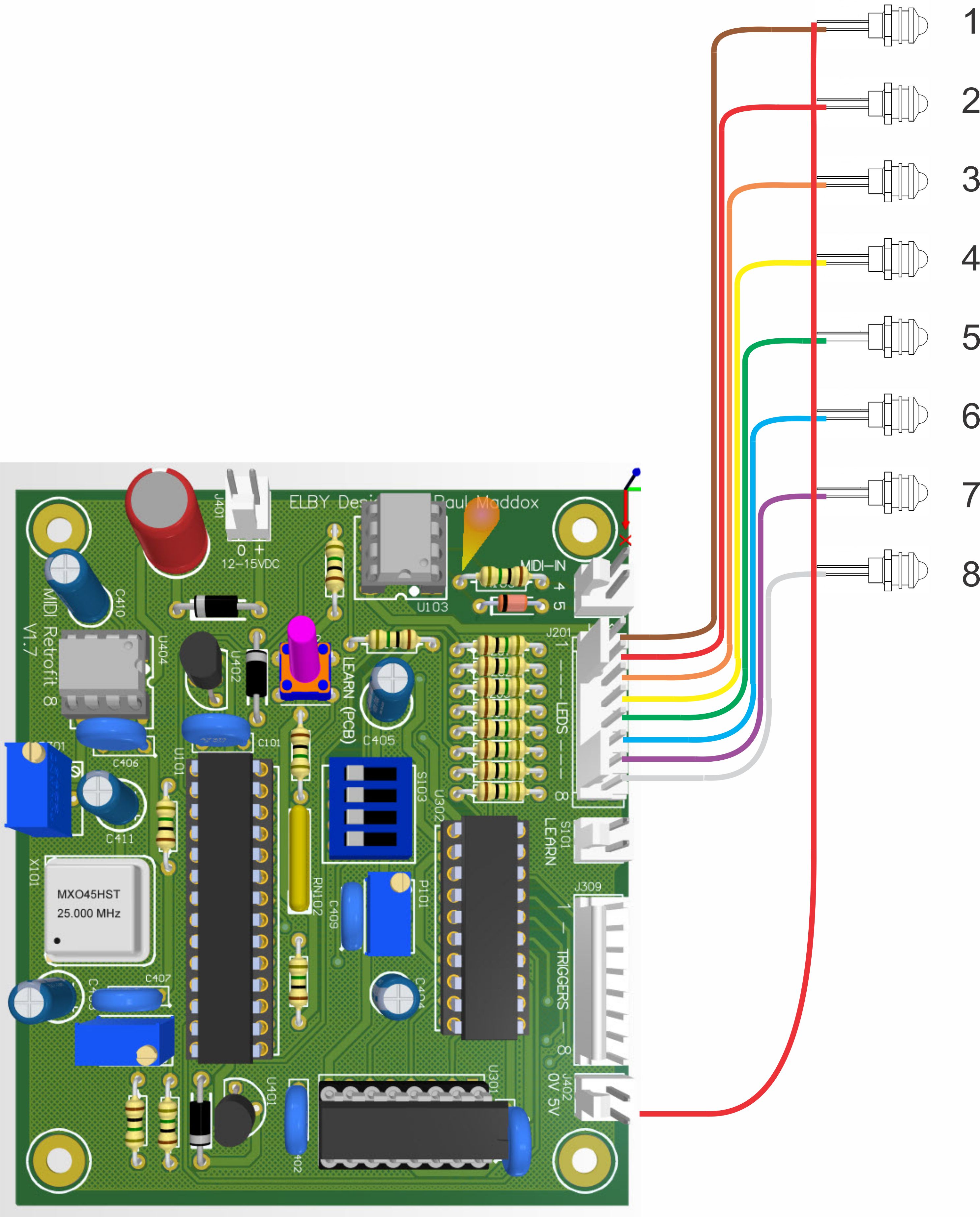
Connect, if required, the cathodes of the 8 LEDs to J201 as shown at left. Common all the anodes to J402_2.
|
|
Wiring Guide for a Simmons SDS-V


