Build Guide - PCB Assembly

Tools Required:-

  • Philips Head Screwdriver to suit M3

  • Small spanner to hold M3 Nuts during insertion

  • M5 Allen Key for Front Panel/Handle mounting bolts

Start by assembling the back panel

Attach 2x Support Rails to the Rear Panel using M3x6mm Bolts and M3 nuts

Install all components on to the rear panel

Mount the rear panel assembly to the 2 side panels using 4x M3 Flange Screws.
Ensure that the 3 rows of slots on each Side Panel are at the bottom of the case

You can either mount the rear panel assembly flush to the outside edge of the Side Panel or to the back of the slot (this will help protect connectors from being squashed and provide more clearance at the back of the unit).

There are two options for mounting the Front Panel:-
  1. Using the 2 carry handles supplied - recommended. Fitting these front handles will marginally restrict access to the two right-most panel controls.

  2. Using M5 bolts and M5 nuts, mounting the bolts from the front panel side.

Fit the Front Panel using your chosen method. Before finally tightening the securing bolts, ensure that the Front Panel is centred vertically to the enclosure.

NB: If you wish to change your mounting option you will need to remove the Panel PCB from the Front Panel to be able to gain easy access to the mounting points inside the enclosure.

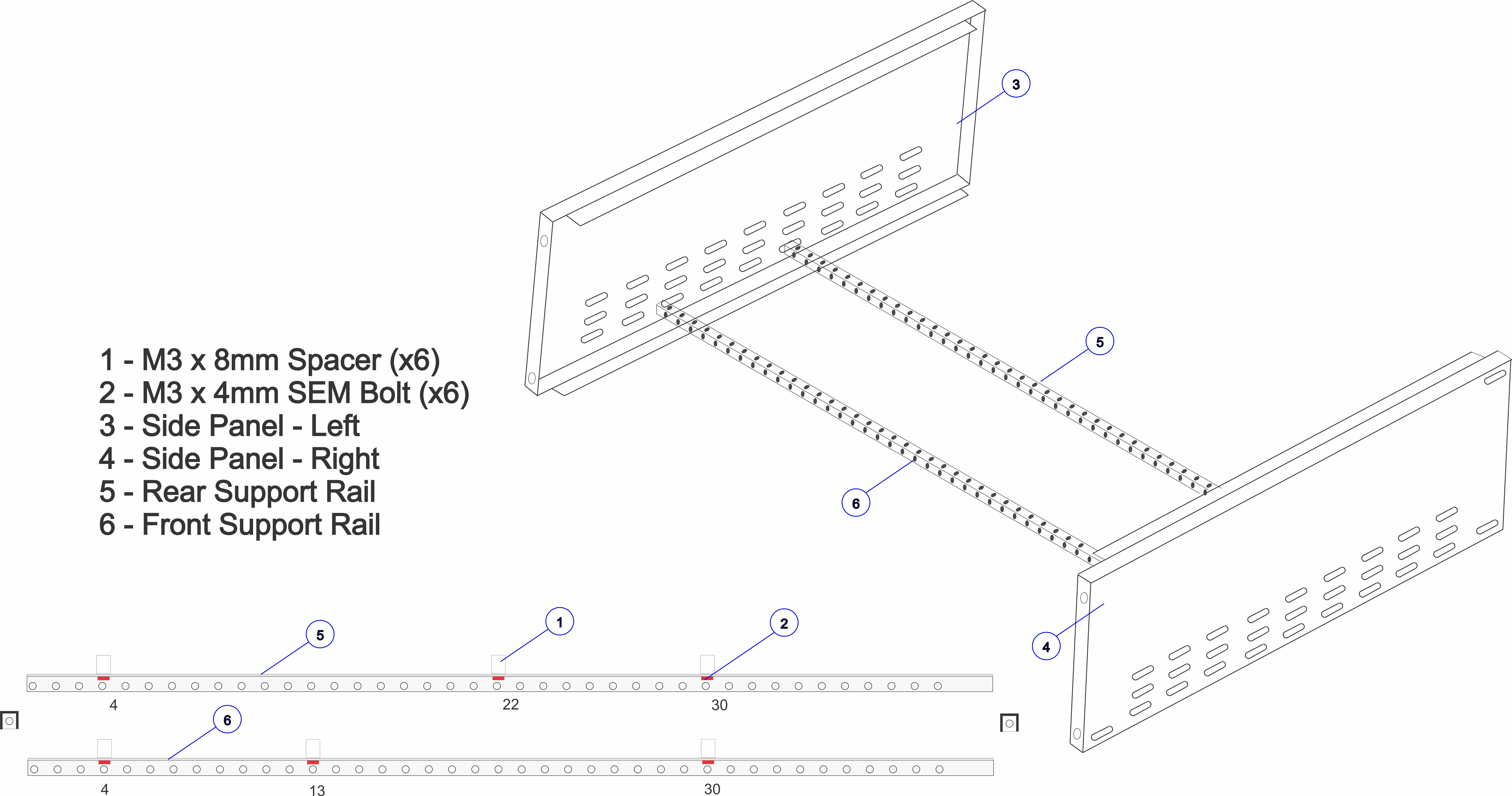
Counting from the left of each rail, fit M3x8mm Spacers using M3x4mm SEM Screws at positions 4 and 30 on to 2x Support Rails.

Fit M3x8mm Spacers at position 13 on the front Support Rail and position 22 on the rear Support rail and secure using M3x4mm SEM Screws.

Install the front Support Rail to the side panels using 2x M3 Flange Screws in the 4th slot from the front, leave the screws loose to allow repositioning of the rails.

Install the rear Support Rail to the side panels using 2x M3 Flange Screws in the 8th slot from the front, leave the screws loose to allow repositioning of the rails.


Your unit should now look like this and be ready for the installation of the PCB assemblies and final wiring

  1. If not already done, remove the protective film from the LCD
  2. Fit the shakeproof washers to all of the pots
  3. Install the Display PCB being careful to guide the LEDs in to their respective lens mounts
  4. Secure using the supplied nuts

  1. Position the MonoWave PCB on the spacers on the 2x Support Rails and secure using 4x M3x6mm Screws
  2. Tighten the 4x M3 Flange Screws for the Support Rails

Fit the 3x IDC Cables between the Main board and display board.
The central and right-hand cables should be folded to allow them to sit neatly in the chassis.

Drawings for the 3 cables:

The complete MonoWave assembly (earlier version of parts are shown)

The MonoWave should now be calibrated and once complete the top and bottom cover plates can be fitted using M3 Flange Screws.


Email:  elby-designs@bigpond.com
© Copyright 2000. All rights reserved.     Revised: June 22, 2024