If not done in the factory, cut the track on the component layer at the point marked 'X' on the overlay
- Fit all components as per the BOM noting that C1001 and C801 should be laid flat to the PCB to minimise component height
-
R2 should be positioned over the cut-out in the PCB and raised to be about 2mm clear of the PCB or by using the ceramic spacers supplied in our kits.
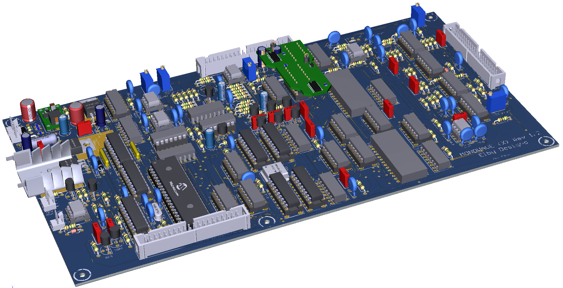
- Refer to the 3D Model for positioning of the wire links in P801 and P1001
- Fit R404 to the underside of the PCB as indicated in the BOM and 3D Model
- Assemble the EG FIX PCB as per the BOM
- Attach wires (approximately 5cm long) to pads J3 and J4
- Mount the sub-assembly in to the sockets for U803 and U1003
- Cut and trim the wires and solder to the diodes D801 and D1001 and as shown on the overlay