|
for music synthesizers.
 
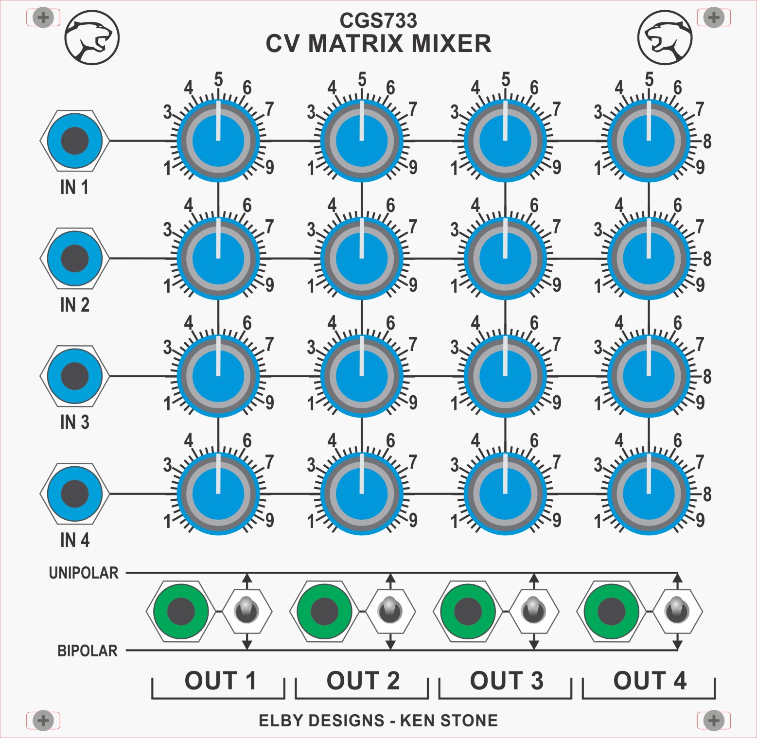
The matrix mixer is a four input, multiple output bipolar or unipolar DC coupled mixer, for mixing control voltages or audio signals. In cases where you require several different mixes from a common set of signals, this module is ideal. Each output can be independently switched to operate in unipolar or bipolar mode. When in unipolar mode, all pots feeding that output behave in regular fashion, that is when the knob is fully counter-clockwise, no signal from the associated input passes into the mix. As the knob is advanced clockwise, a greater portion of the signal passes into the mix. In bipolar mode, each knob has a zero position mid-way through it's travel. Turning the knob anti-clockwise will add an increasing portion of a negative (inverted) version of the signal at the corresponding input, while turning the knob clockwise will add an increasing portion of the original signal to the mix. A little on how it works: 
Input buffers for the Matrix Mixer.
As is obvious from the circuit diagram, the matrix mixer is little more than a group of standard op-amp summing circuits and buffers. Any signal applied to an input is first buffered by a voltage follower based on a TL071 op-amp so as to not load down the output of whatever module is driving it. The buffered signal from each input are then fed to the inputs of five identical column mixers. The pots steer the signal to either the first or second op-amp of the mixer in bipolar mode, or the first op-amp or ground in unipolar mode. Any signal that is sent to the first op-amp is inverted, then mixed with any signal being sent to the second op-amp. This signal is then inverted again, and sent to the output jack. Construction
The component overlays. When you are happy with the printed circuit boards, construction can proceed as normal, starting with the resistors first, followed by the IC socket if used, then moving onto the taller components. Take particular care with the orientation of the polarized components such as electrolytics, diodes, transistors and ICs. When inserting ICs into sockets, take care not to accidentally bend any of the pins under the chip. Also, make sure the notch on the chip is aligned with the notch marked on the PCB overlay. Column boards are connected to the main board via a 16 way ribbon cable and 16 pin insulation displacement connectors. For each additional column board used, you need only add another connector to the same ribbon cable.

The value of the pot used in the processor will affect the response of the pot. The pot itself MUST be linear. For example, a 50k will give a slightly anti-log response.
Notes:
Article, art & design copyright 2008 by Ken Stone |