|
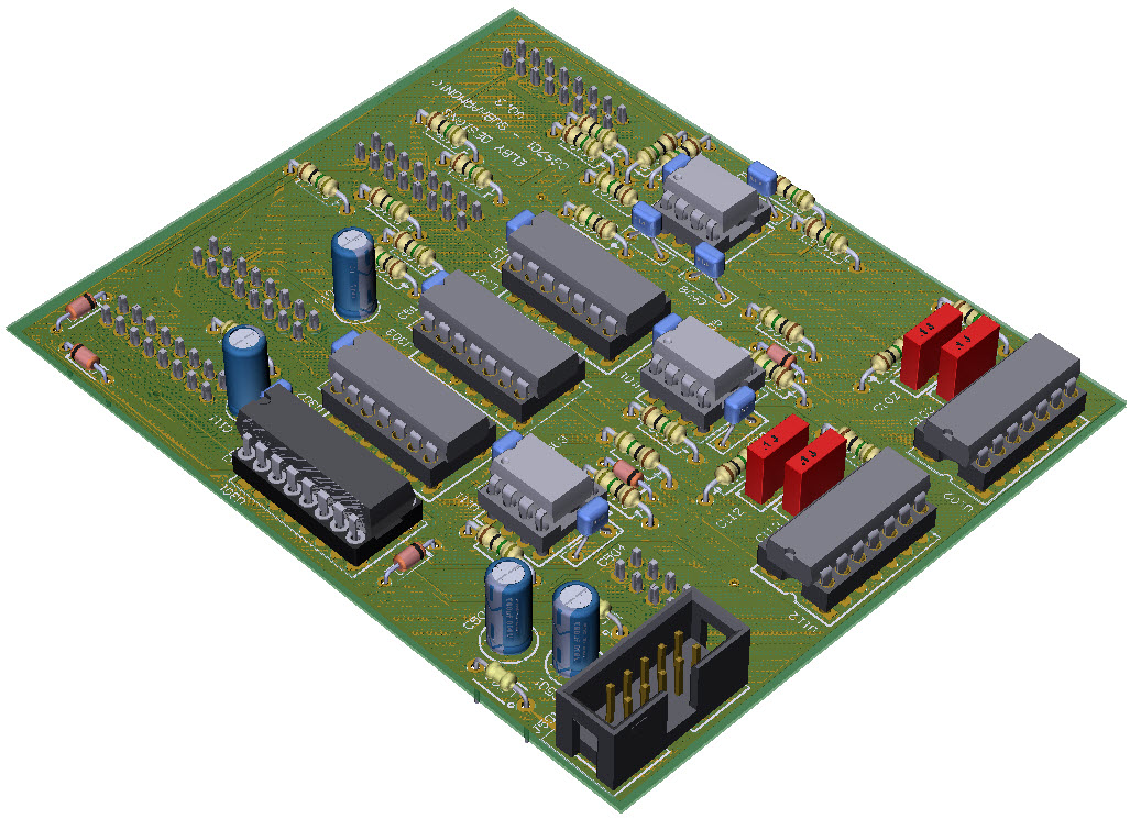
3D Model |
Overlay |
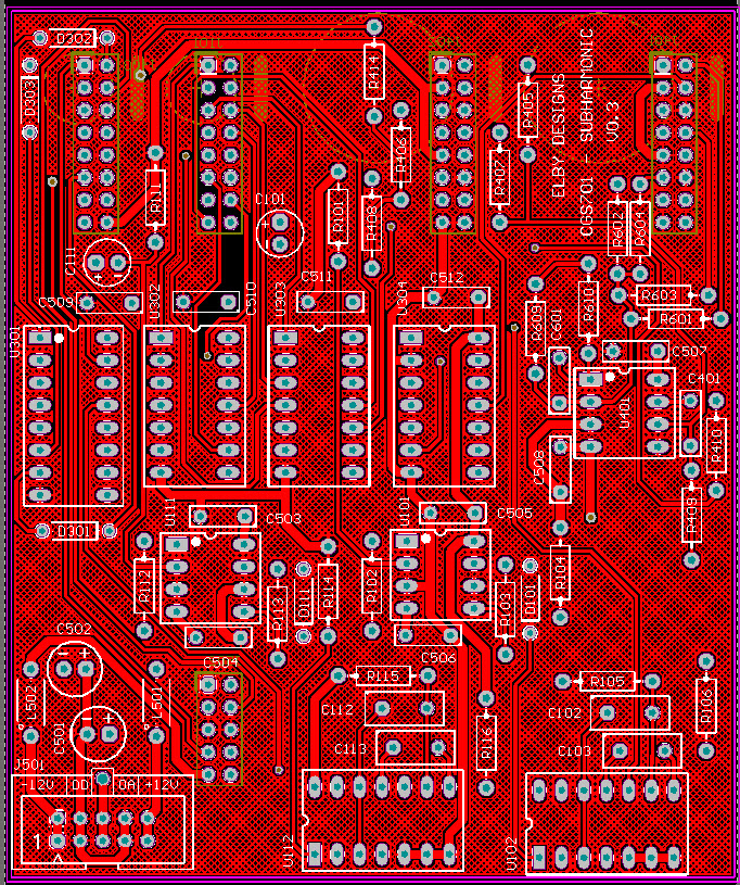
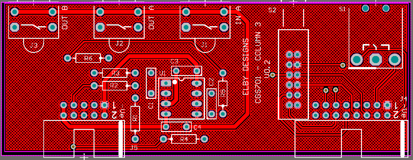
Plan View |
|
|
|
|
|
|
|
|
Column 1/2 PCB |
|
|
|
Column 4 PCB |
|
|
|
Constructors should refer to the Component Overlays along with,
the Bill of Materials for the current value of all components, and
the General Construction Notes for general PCB assembly guidelines.
- Assemble Column 1 and Column 2 PCBs
- Fit all parts except for S1 and S2 on the Column 3 PCB
- Fit all parts except for S1 and S2 on the Column 4 PCB
- Fit S1 but do not solder
- Offer the assembly up to the panel and secure using the supplied nuts
- Check that the body of the switch is square to the PCB and solder into place, soldering on both sides of the PCB
- Fit the switch cap to S2 and then install it on to the Column 3 PCB
- Make sure the switch is sitting square to the panel and solder tack a front and rear leg
- Make sure the switch action is smooth adjusting the switch position as needed and then solder in to place
- Install U1
- Fit S1 and S2 to the Column 4 PCB but do not solder
- Make sure the switch bodies are sitting square to the PCB and solder in to place, soldering on both sides of the PCB
- Install the Column 1 and Column 2 assemblies
- Fit the Main PCB ensuring the IDC connectors are correctly aligned.

