The ED115 comprises a Noise Generator and a Sample & Hold.
NOISE GENERATORThe Noise Generator generates a [WHITE] noise output which is also fed in to a series of filters to generate a [PINK] output a [VIOLET] output and a [RANDOM] output.
WHITE Noise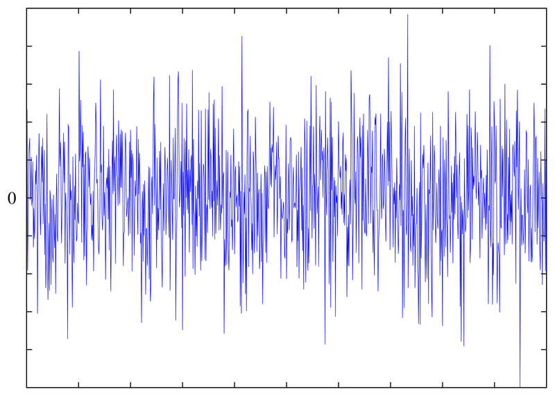
The White Noise generator operation is based on the noise generated by the Zener breakdown phenomenon in a BJT inversely polarized base-collector junction. In other words, such shot noise involves the statistical fluctuations of the current flow present in the bipolar transistor.The generator makes use of a common 2N2907 biased by a constant current source. To increase the amount of shot noise attainable, the collector of the 2N2907 is left open and the base-emitter is reverse-biased. That is, the BJT is connected as a zener diode to exploit the reverse breakdown phenomenon. With this configuration, the reverse breakdown voltage exhibited by the emitter-base junction can be easily observed using an ordinary spectrum analyser. The attainable bandwidth is about 300MHz, and the power output is about -70 dBm. This signal is passed through an amplifier which sets the output voltage at a nominal 8V peak-peak.
Typical White Noise Signal
PINK Noise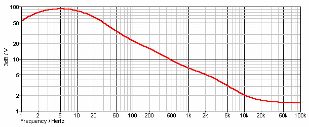
The PINK filter is a 3dB/octave filter which is pretty linear across the range 10Hz to 15kHz to within 1dB across the full 50dB range. A final stage buffer-amplifier sets the output level to around 8V peak-to-peak.
Frequency plot of PINK Noise
VIOLET Noise
The VIOLET filter has two frequency dependent elements in the feedback path. The first feedback element on its own would produce a 6dB/octave rise in the gain of the amplifier from 0dB at 0Hz via 3dB at 9Hz to 20dB at 90Hz. The second feedback element on its own would produce a 6dB/octave fall in gain from 0Hz to 1kHz above which the gain would remain constant at 0dB.The combined effect of these feedback elements is that below 90Hz the 6dB/ocatve rise and 6dB/octave fall cancel out, giving a gain of 20dB. Above 90Hz the gain falls at 6dB/octave to 0dB at 1kHz, above which it remains constant. The result being that the bass end of the noise spectrum is boosted, and is available at the VIOLET output. A final stage buffer-amplifier sets the output level to around 8V peak-to-peak.The ED116 allows the [RED] and [BLUE] mix of the [VIOLET] output to be user adjusted through panel controls.
RANDOM Noise
The RANDOM noise output is a low-pass 2nd-order Sallen-Key filter which passes only the very low frequency components to produce an extremely low frequency `random voltage'. Fluctuations of the random voltage are displayed on a LED indicator which will change from RED to GREEN as the output switches above and below 0V.The ED116 allows the [RATE] of change of the [RANDOM] output to be user adjusted through panel controls .
SAMPLE & HOLD
The Sample & Hold section is derived from that used in the IF109 – TGTSH from Ian Fritz and takes an instantaneous sample of the input signal and presents it to the [OUT] output. The resultant output is a `random voltage' that changes on each positive edge of the [SAMPLE] input which is indicated by the [SAMPLE] LED. The [SAMPLE] connector is normalised to the [RANDOM] output of the NOISE section while the IN connector is normalised to the [WHITE] noise output. Inserting a jack in to any of these connectors will allow an external signal to be used instead.
The [SAMPLE] input requires a positive-edge trigger signal that should swing from 0V to greater than 1V. The [S&H IN] input is DC coupled and will accept CV and AC signals.

ED115 Signal Paths |

