-
Set the [RATE] control to minimum
-
Fit jumper JP1 in to the 'CAL' position
-
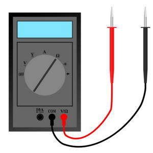
Monitor the output of U2 at test point TP1 using a multimeter set to the 1V DC range
-
It will probably exhibit a tendency to drift positive or negative and the voltage will eventually settle at +12V or -12V
-
Reset the output voltage by momentarily shorting JP2
-
Adjust P4 until the voltage remains stable with minimal drift for a period of several seconds
-
Repeat steps (5) and (6), progressively switching the multimeter to more sensitive ranges, until the drift is only a few millivolts over several seconds
-
Fit JP1 in to the 'RUN' position and ensure JP2 is open