|
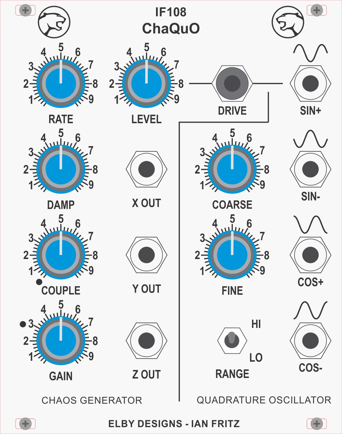
The main function of this module is a versatile chaotic signal generator. Chaotic signals are signals that have varying degrees of interesting irregularity without actually becoming random. This CG is an analog electronic simulation of the classical driven double potential-well problem, with the addition of extra gain in the circuit loop, and an extra cross-coupling path to extend the range of chaotic patterns available. The double-well system is a second-order system and therefore requires an external driving signal. This is provided by the second part of the module, a sinusoidal quadrature oscillator. The two parts of the module may be used together or separately. The CG may be driven by any output of the built-in QO or by any external oscillator. The QO may drive the CG or be used independently as a four-phase oscillator for the usual spatial modulation and other applications. Both parts of the module are manually controlled, to provide a compact, cost-effective unit. The QO has a frequency span of ~0.03Hz to ~3kHz in two overlapping ranges.
Setup and Operation: The output levels of the QO are between 4V and 6V, depending on frequency. The variation is mainly due to imperfect tracking of the dual pots. The signal may be checked on an oscilloscope or by ear. On the high- frequency range the signal should span about 3Hz to 3kHz, and it should look and sound like a high-purity sine wave. On the low-frequency range the signal should span about 0.03Hz (33 sec period) to 30Hz. Operation may be verified on a scope or by using the signal to modulate a VCO. Correct quadrature phases may be verified with a dual-trace scope. One warning: the QO takes about 30 cycles to stabilize upon power up. So if you turn it on and it doesn't seem to be running, just turn it up to a higher frequency to get it going, and then back down if you want. Once started it follows changes quite well. The CG has a large number of unfamiliar controls, and not all setting of these controls will give oscillations. But with a systematic approach the user can quickly learn the basics of operating the unit. It's easiest to do this with a scope, especially if it can make Lissajou patterns, but it can also be done by ear. The best place to start, especially if learning by ear, is to think of the CG as a complex kind of LFO. So start out by hooking up the [X OUT]and/or [Y OUT] to the FM inputs of some VCOs/VCFs/etc., set to a comfortable audio signal. This particular CG requires an external drive signal to produce chaotic oscillations. The driving signal may be the QO or any other oscillator. By default, the IF108–ChaQuO has the [SIN+] output connected to the [DRIVE] input. Set the Drive [LEVEL] at 50% of full scale (FS) to start. Two of the controls may be thought of as advanced controls, and for now should be set at special positions as indicated by the 'dot' and left there. These are the [COUPLE] control and the [GAIN] control. (With these settings, the CG is the same as the EZChaos circuit, which many users will already be familiar with.) Next set the [RATE] control at 50% FS. This control is analagous to the frequency control of an LFO or VCO. The higher the rate, the faster the system will run, everything else being equal. Next set the [DAMP] control to 30% FS. Damping can be thought of as the opposite of resonance in a filter. The less the damping the "wilder" the chaos gets and vice versa. Now you are set to look for the chaotic regions of the system! You will do this by varying the frequency of the driving oscillator. Start at a fairly high frequency and tune it downward until you start to hear a modulation of your audio patch. On the scope look for a small oval to appear. At this point, the CG is executing nearly sinusoidal oscillations. Continue lowering the drive frequency (slowly) and you will hear the modulation become slower and deeper until you reach a point where the modulated signal becomes irregular and jittery. You're there! That's what chaotic control sounds like. Continue to decrease the drive frequency slowly and you will hear several regions of regular (periodic) and irregular (chaotic) oscillations. Eventually you will reach an end point where the signal is regularly bouncing between two regions. On the scope this looks like a kind of double spiral. From here experiment with the effects of all the controls, one at a time. Tune back into the chaotic region and look at how the signal varies as you change either the drive level or the damping. Remember, if you get lost, you can always get back to a base position by following the procedure above. The [GAIN] and [COUPLE] controls can be explored when you have a good feel for the other controls. Try changing the [GAIN] first and see how it changes the patterns you got before. Finally you can start turning the [COUPLE] control up. This adds another signal path to the system and can easily get out of control. As you increase the [COUPLE] you generally need to increase the [GAIN] to keep the system from running to the rails. Another "minor" detail is that with [COUPLE] turned up, the system can self oscillate, i.e. it does not need the drive signal to oscillate. These will not be chaotic oscillations, but still quite interesting, especially when you are in a region where both the self oscillations and the driven ones are competing. From here you are on your own to explore the many uses of the system for modulation, audio effects and so on. Also very important is the use of the chaotic signals to define chaotic timing events, to feed through S/H modules, and for other non-continuous applications.
This video by Ian Fritz is an excellent guide to using the IF108 ChaQuO |


© Copyright 2000. All rights reserved. Revised: August 19, 2023