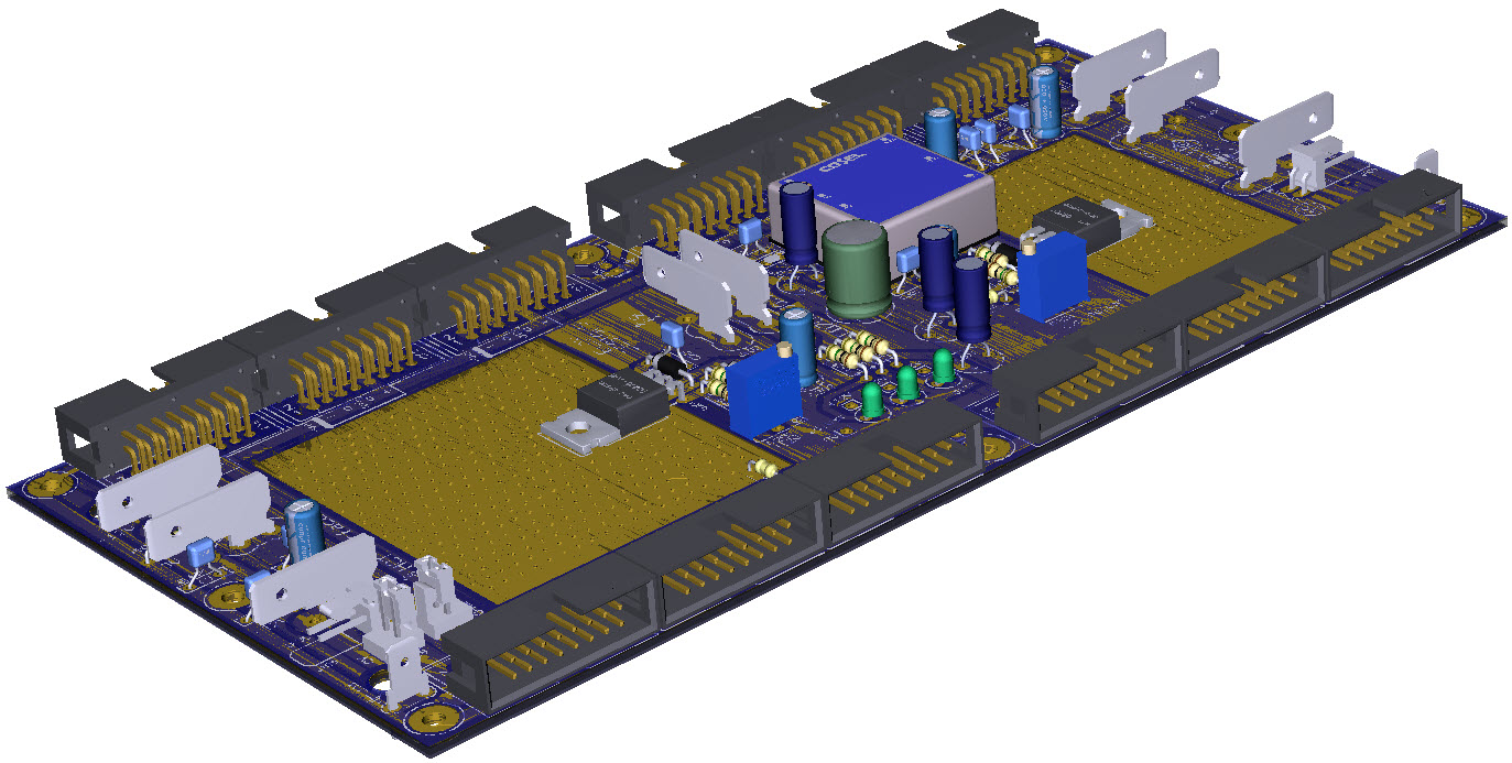
The ED705 is a passive busboard incorporating a dual linear regulator power supply providing +12V @ 1.5A and -12V @ 1.0A and 12 module power outlets.
The ED705H uses right-angle IDC connectors which not only makes it ideal for shallow skiffs, but they also make insertion of cables easier.
The ED705 has +/-12V power connections at both ends allowing multiple ED704 boards to be daisy-chained to support any sized system. A different approach to the design of the distribution rails within the ED705 offers improved performance in multi-board systems with minimal signal loss across the length of the run and enhanced noise immunity. The enhanced design eliminates the need for bulky heatsinks, further enhancing the low-profile design of the board.
The ED705 requires an external 15VDC supply with a nominal rating of 2.4A. "loop-in-loop-out' 15V terminals allow multiple ED705 to be installed in systems requiring large power capacity.
When installing multiple ED705's in a system to increase the overall system loading capacity, the user should be aware that each ED705 must still be limited to within its maximum loading. So, for example, if you have 2x ED705 to give you as +12V 2.5A capacity, you must spread your modules between the ED705's so that neither of them is loaded beyond its 1.5A capacity. This will usually require you to study the power loading figures for each module and totalise the loadings for the modules connected to an ED705.
WIRING NOTES
The ED705 has 3 sets of power in/out terminals, the ones at each end of the PCB are for connecting to passive busboards such as our ED704. Either set can be used to feed power in to the ED704. The other set can then be used to connect to an additional ED704 if needed.
The 3rd set of terminals at the centre of the PCB are for connection to an external 15VDC supply.
We no longer support the 5V rail as a mainline bus and do not recommend extending the 5V rail across multiple busboards (passive or active). If a module is installed that needs an external 5VDC supply we recommend the use of a small 12V-to-5VDC adaptor such as our EURO-5V. If using our EURO5V with [BusBoardENabled] then 5V will be made available to all modules on this busboard.
The CV-GATE circuit is split in to 2 zones, one for the top row of connectors and the other for the bottom row of connectors. Jumpers are supplied factory fitted to J107 and J108 that combine the 2 CV-GATE sections in to a single section.
The eight mounting holes are isolated from the power rails. Two 4.8mm quick-connect tabs (J103 and J104) are provided to allow a dedicated CHASSIS GROUND connection to be made.
The ED705 is also the first powered busboard to implement the EuroSynth Specification and allocate the central 0V pins of the IDC connector to CHASSIS GROUND. When used in a full EuroSynth system this will allow the system to implement a proper CHASSIS GROUND system. The inclusion of one or more EuroRack modules will nullify the CHASSIS GROUND arrangement but not impact or interfere with the operation of those modules.
Wiring Diagram |
