General Build Notes
The following documentation provides general build information for the BoCGS and Voltron panels and assumes the user is using the relevant ELBY Designs Component and Hardware Kits for each panel.
Builders should always refer to the website for detailed build information for each board. Where applicable, we have added additional notes for clarification for each board as it pertains to the BoCGS build.
The panel pictures show the location of the various coloured banana sockets using the colour scheme discussed at the end of this document.
Power Supply
There is, typically, insufficient room in the BUD enclosures to accommodate a power supply so we strongly recommend a separate enclosure be made for a power unit and your BoCGS units powered from it. To this end our BoCGS Full Kits include a 4-pin connector suitable for connection back to the main power unit via a suitably sized power lead. |
 |
Typical consumption figures for the BoCGS are:-
PANEL |
+12V |
-12V |
BOG |
250mA |
200mA |
MARSH |
200mA |
170mA |
SWAMP |
700mA |
50mA |
Voltron 2 |
290mA |
170mA |
Voltron 3 |
110mA |
50mA |
Voltron 6 |
230mA |
130mA |
Voltron 7 |
320mA |
250mA |
A suitable power supply would, typically, deliver, as a minimum, +12V @ 1.2A and -12V @ 450mA to power a typical 3-boat system like the BoCGS. Our PSU-10a is ideal as an external supply for powering up to 3 boats. The PSU-10 requires an external laptop style supply rated to a minimum of 15VDC @ 2.4A. The PSU-10 is equipped with 3x 4-pin DC connectors.
For a single boat power solution we would suggest our PSU-8a. This requires a well-regulated 12VDC power supply (preferably linear) and should comfortably handle up to 2 boats. However if there is the possibility of future expansion then the PSU-10 is a more viable solution.
Module Power Connectors
Currently, most CGS PCBs use a 4-pin 0.156” MOLEX-type connector but we are slowly replacing these with a more compact 3-pin 0.1” MOLEX-type connectors
The power signals for the 4-pin connector are:
• Pin 1 = +12V
• Pin 2 = 0V
• Pin 3 = 0V
• Pin 4 = -12V
while on the 3-pin connector it is
• Pin 1 = +12V
• Pin 2 = 0V
• Pin 3 = -12V |
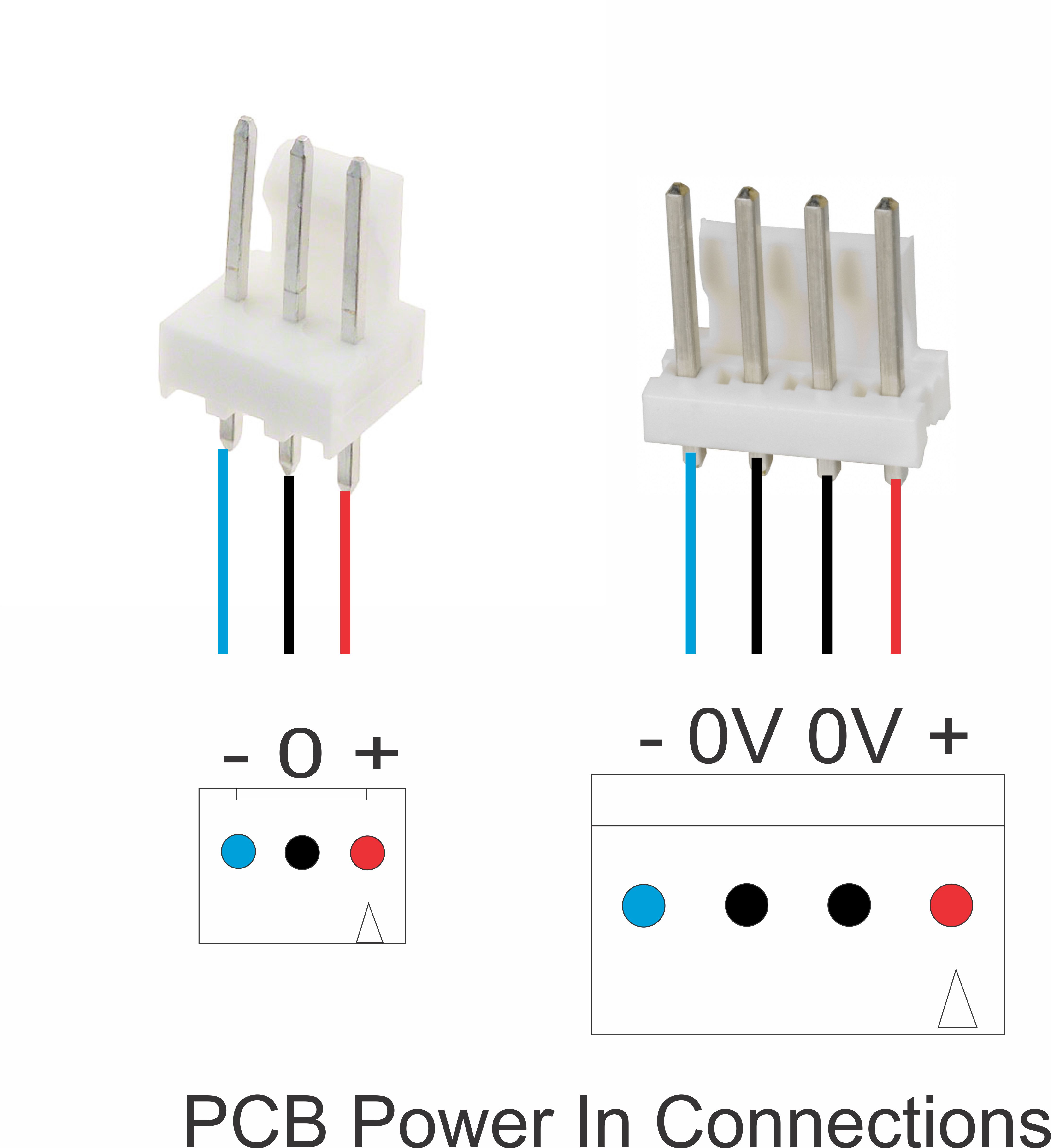 |
This change will allow for the use of a smaller, sized crimp that will work better with the cable typically used in builds like this and increase the available space on PCBs for the main circuitry.
CGS420 DC Splitter
To facilitate improved noise immunity and intra-module contamination, we have introduced the CGS420 DC Splitter. This simply splits the 4 incoming power rails at the MIC connector into two separate 3-pin connectors with one being assigned to the ‘upper’ CGS391 Rail and the other to the ‘lower’ CGS391 Rail. Although the +12V and -12V power rails are shared between the two connectors, they each use a separate 0V pin on the MIC connector. This separated 0V rail remains intact all the way back to the main DC power supply, typically our PSU10, where the two 0V rails are shorted together to form a common node. Further, one of the CGS391 Rails is assigned to ‘cleaner’ analogue modules while the other CGS391 Rail is assigned to ‘dirtier’ and/or digital modules. This separation helps reduce power supply noise problems by reducing common-mode issues.
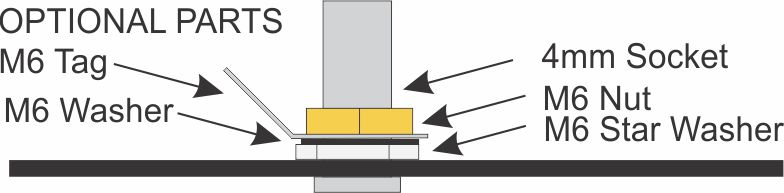
CHASSIS GROUNDING
As most power supplies used have a floating output there is no inbuilt mechanism to prevent static build-up. To help circumvent this, our boats include the option to fit a 4mm CHASSIS GROUND connector. This should be connected via a suitable EARTH cable terminated with a 4mm plug at the boat and to a suitable and safe EARTH point at the other.
ELBY Design boats have the raw aluminimum of the boat exposed in the immediate area around the Chassis and so electrical contact is made through the star washer which penetrates the surface layer the aluminium.
If you need to connect other components to CHASSIS Ground, such as the Front Panel, then the optional M6 Tag can be fitted and a suitable gauge 'ground wire' attached for.
|
|
DC Power In
The MIC-4 connector pin-out is
• Pin 1 = -12V
• Pin 2 = 0V
• Pin 3 = 0V
• Pin 4 = +12V
NB: This is the REVERSE of the 4-pin MOLEX connectors that
connect to the module PCBs. |
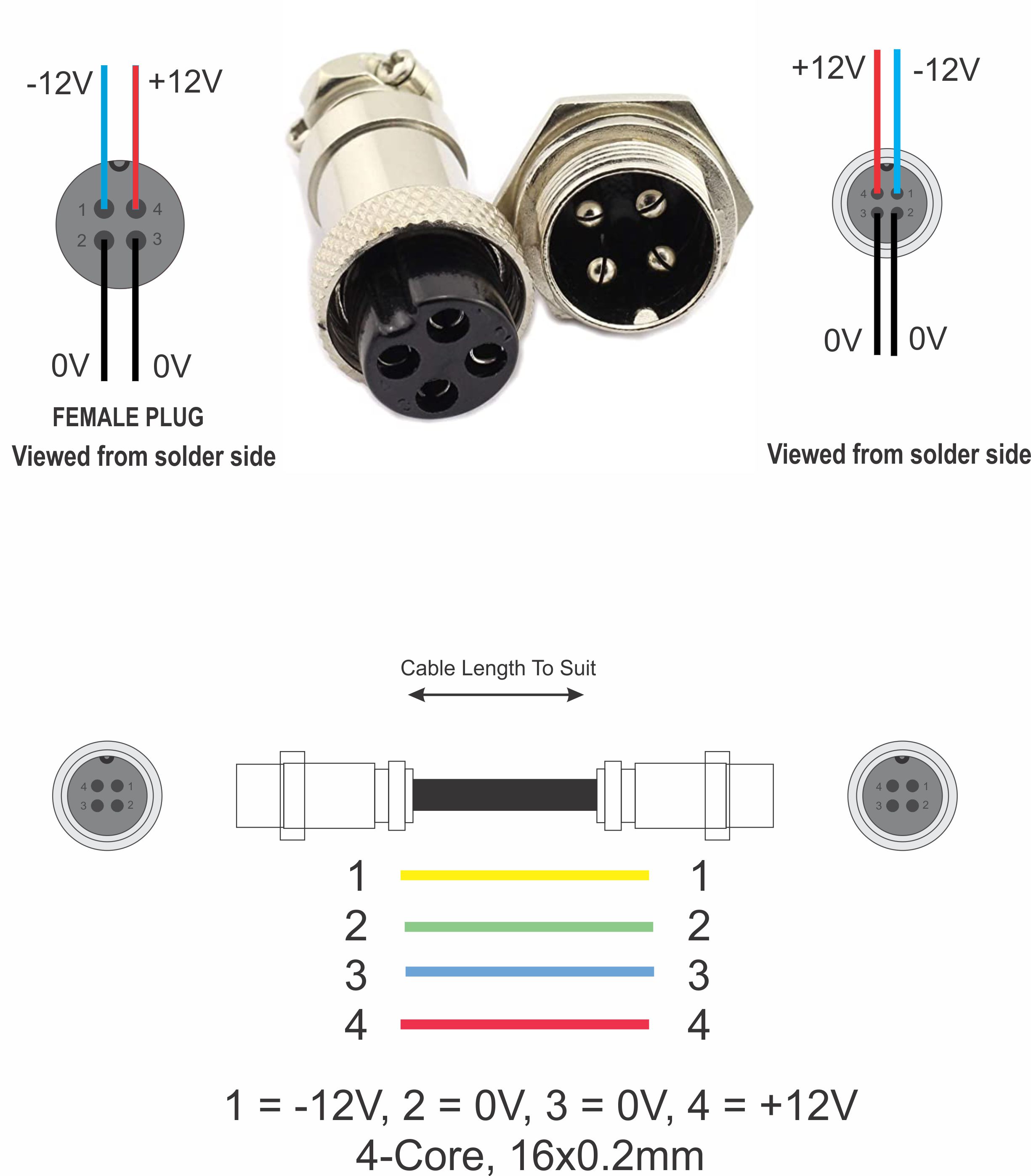 |
NB: If making your own DC-DC cable for connecting to our boats using the recommended 4-pin MIC connectors you should:-
• use a 4-core cable
• make sure that you terminate both pin 2 & pin 3 to the 0V terminal
Patch Point Colour Scheme
The BOCGS Hardware Kits use an enhanced colour scheme for the 4mm sockets. The new scheme provides for differentiation between Inputs and outputs as well as AC and DC signals. Although there is no hard and fast definition, one of the generally adopted SERGE Modular schemes uses:-
• BLACK = AC,
• BLUE = DC,
• RED = LOGIC, and
• PURPLE = SYNC.
This scheme doesn’t differentiate between INPUT and OUTPUT so the above colours have been assigned to INPUTs while WHITE, GREEN and YELLOW have, respectively, been added as OUTPUTs to give:-
SYNC signals now fall under the LOGIC category and so use RED and YELLOW.
All knobs are a Davies clone and are BLACK.
Cable Specification and Colour Scheme
To assist with fault-finding and cable tracing, it is prudent to adopt a colour coding scheme. ELBY Designs is implementing the following colour scheme for its BoCGS/Voltron wiring diagrams:-
Power Rails
There are 3 main power rails used in these systems being +12V, 0V & -12V the adopted colour codes for these are:
Module PCB to Power Rail (eg CGS391)
|
7/0.2mm (24AWG) (*) |
Colour |
+12V |
 |
Red with White Stripe |
0V |
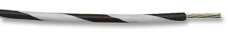 |
Black with White Stripe |
-12V |
 |
Blue with Grey Stripe |
Power Rail (eg CGS391) to Power IN
|
16/0.2mm (20AWG) (**) |
Colour |
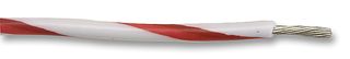
+12V |
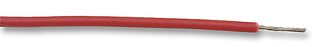 |
Red |
0V |
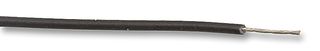 |
Black |
-12V |
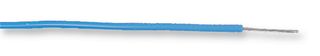 |
Blue |
General Wiring
All other wiring uses a plain colour wire which is also 7/0.2mm (24AWG), Tinned Copper, PVC coated.
(*) We recommend using 7/0.2mm/24AWG with a maximum outside diameter of 1.2mm. We also recommend using RED, BLACK and BLUE wires to quickly identify the +12V, 0V and -12V power rails respectively, if needed for later diagnosis. In our kits we used a striped wire for these 3 wires to help differentiate them from the standard signal wires.
(**) We recommend using 16/0.2/20AWG with a maximum outside diameter of 1.55mm. We also recommend using RED, BLACK and BLUE wires to quickly identify the +12V, 0V and -12V power rails respectively, if needed for later diagnosis.
The above wire sizes are our recommended sizes but other gauges of wire may be used as long as the builder confirms that the selected wire will fit the PCB wire-holes (if used) and that any crimp connectors used have the correct crimp diameter range to suit the wire gauge selected.
Main Wiring Colour Scheme
The simplest colour scheme uses the common resistor colour code to number the pins of the PCB footprint. So, for example, a pot, typically, has three pins and so these are assigned the colours 1 = Brown, 2 = Red, 3 = Orange. A dual-gang pot would have 6 pins with the 2nd pot having the colours 4 = Yellow, 5 = Green & 6 = Blue. As all jacks have only one pin, this would mean an abundance of brown wires so it is suggested that the wires to the jacks represents the nominal function of that jack and hence follows the ‘jack function colour scheme’ ie Blue jacks have a Blue wire while Red jacks have a Red wire.
If a component has one or more of its pins connected to a power rail, then that pin will use the relevant ‘power colour’ wire. For example, a pot with all three pins acting as ‘signal pins’ (such as in the gain loop of an opamp) it will use Brown, Red, Orange but if, for example, the ‘end’ pins are connected to +12V and -12V then the colour connections would be Red/White, Red, Blue/White.
PCB Footprints
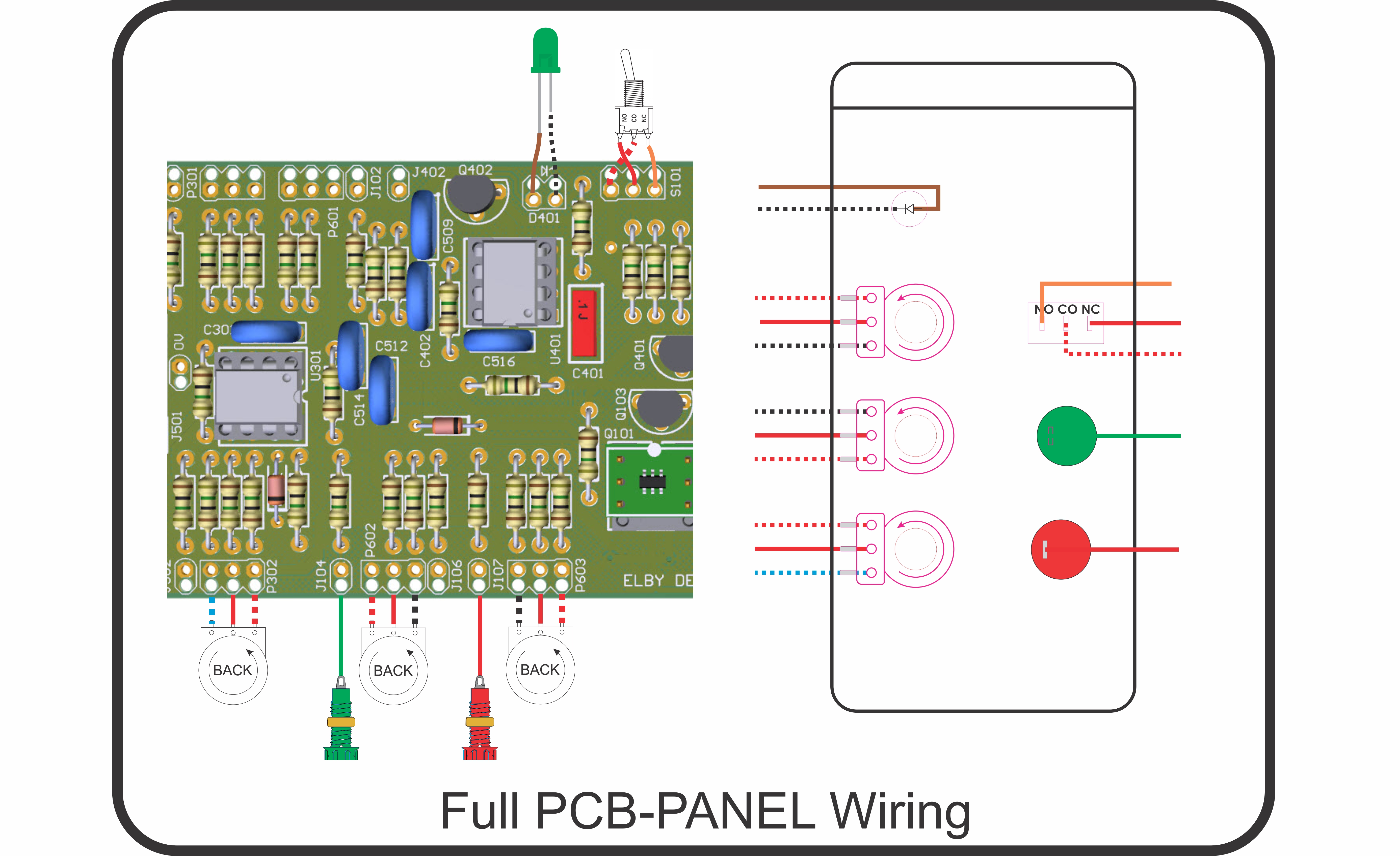
The ELBY Designs CGS PCBs use full component pinouts (ie each pin on the component has a matching pad on the PCB footprint) that allows for a ‘FULL PCB-PANEL’ wiring approach. PCB footprints use the following basic single pin layout:-
 |
This is, by default, Pin 1 and is identified by the chamfered corner at top left. |
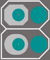 |
A 2-pin footprint will look like this. Again Pin 1 is at the top and indicated by the chamfered corner. |
This diagram shows typical footprints with their standard colour-coded wires and some typical panel component connections.
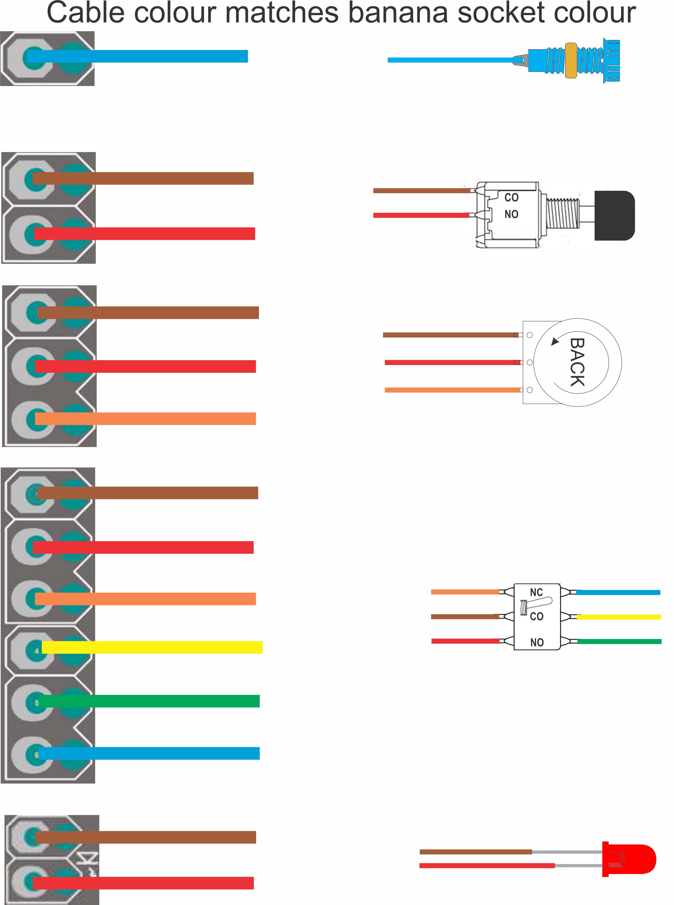
Note that the jack is an exception to the colour-coding, as described above.
PCB-PANEL Wiring
As discussed above ELBY Designs CGS PCBs use full component pinouts that allow for a ‘FULL PCB-PANEL’ wiring approach. With this approach ALL of the component pins are directly wired to their respective pads on the PCB. This facilitates for easier servicing as each component can be handled completely without interfering with any of the wiring to other components. This method will require some longer lengths of wiring.
The diagram to the right shows some wiring using this approach. As you can see, every component pin has a direct-to-PCB connection.
|
 |
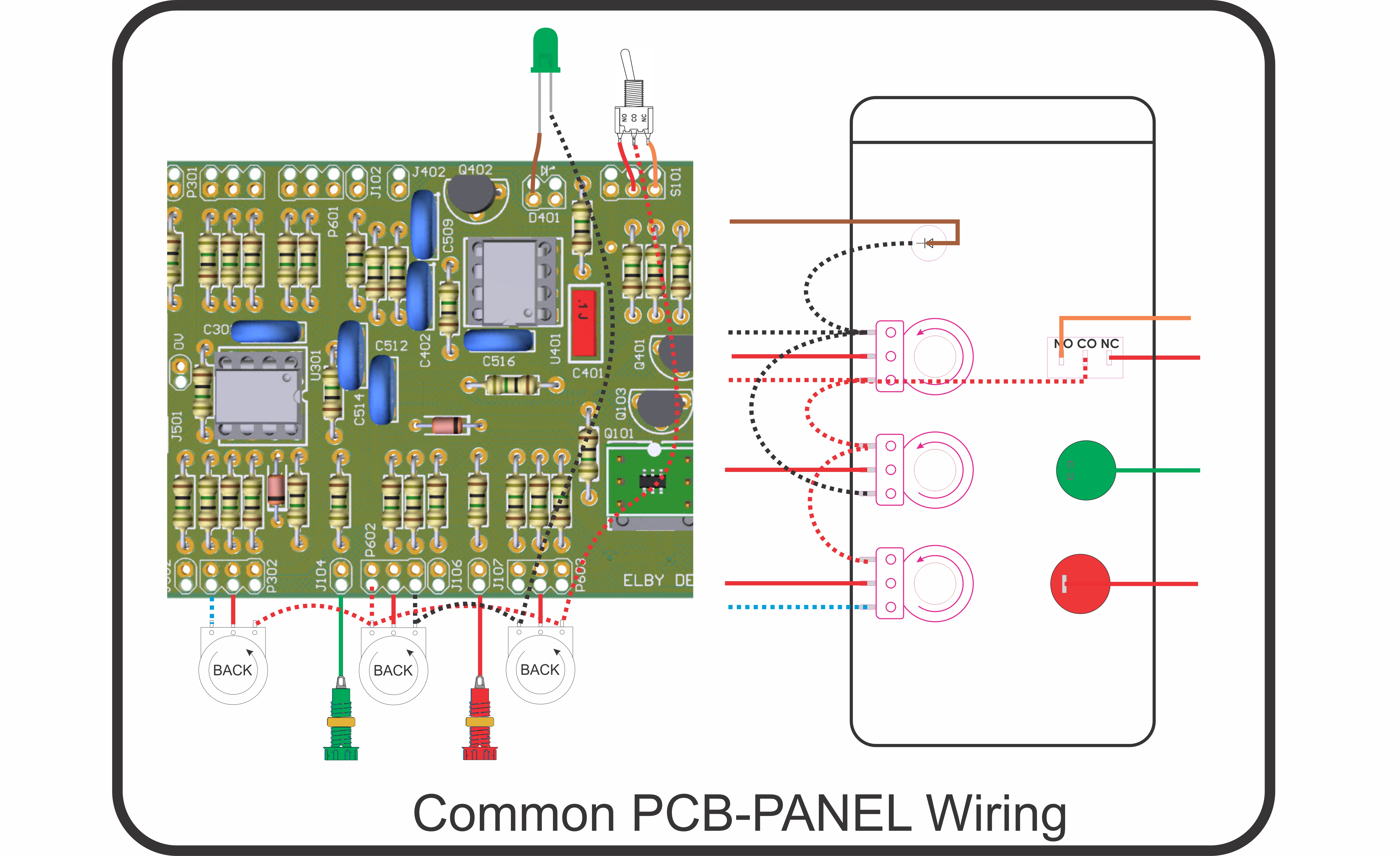
An alternative approach makes use of any common connections to reduce the amount of wiring between the PANEL and the PCB. This is shown in the diagram to the right.
You can see that several 0V and +12V connections exist but these have been connected together with a single wire for each connection running to the PCB. The only real benefit of this approach is a reduction in the amount of wire needed for the complete wiring.
It is important to note that this method must NOT be used to provide common connections to other modules i.e. you must not share +12V, 0V or -12V conenctions between different modules.
|
 |
General Assembly
Start by populating the Front Panel with the pots, then switches, jacks and finally LEDs.
- Pots should be installed with their pins pointing towards the end of the boat. It doesn’t really matter which end you opt for but all pots should point the same way.
- After the jacks have been installed we recommend folding their solder tabs over to about 45º this will help prevent the contact from moving while being soldered.
- LEDs should, generally, be installed with their pins horizontally aligned to the top/bottom edge and with their CATHODEs all on the same side (Most LEDs have relatively long legs and we recommend trimming these down to about 5mm and 7mm for the ANODE and CATHODE respectively).
The next stage of construction should be the CGS391 Rails and Boat:-
- Start by assembling the Power Input PCB (CGS420) by installing the two 3-way MTA connectors and the 4-pin MIC connector
- Assign one of the CGS391 PCBs as the ‘Upper Rail’ and the other as the ‘Lower Rail’
- Cut 3x 15cm lengths (check the associated Power Wiring diagram for any modules that need a longer cable length) of multi-strand equipment wire (*) for each module that is being installed
- Strip and twist ~5mm from one end of each wire
- Referring to the relevant ‘power-wiring’ diagram for the boat, terminate the wires into their respective pads on the CGS391 (insert from the Component Side, solder and then feed the wire through its strain-relief hole)
- Within each group of 3 wires, trim the longer wires to the same length as the shortest wire
- Strip ~3mm off the free ends of the wires and then fit crimps
- Cut 3x 9cm and 3x 12cm lengths of multi-strand equipment wire (**)
- Strip and twist ~5mm of one end of each wire
- Terminate the wires in to the J17 pads of the ‘upper rail’ (insert from the Component Side)
- Terminate the wires in to the J18 pads of the ‘lower rail’ (insert from the Component Side)
- Feed the wires through their respective strain-relief holes
- Trim the longer wires on each CGS391 to the same length
- Strip ~3mm off the other ends of the wires and then fit crimps, checking the wiring diagram and BOM for the correct crimp sizes
- Complete assembly of the CGS391 by fitting crimp housings to the module power cables
- Refer to the associated PCB Mounting diagram and BOM and fit M3 bolts and spacer on to the CGS391 PCBs at the points indicated to support the module PCBs
- Install M3 bolts and spacers to support the CGS391 PCBs as stated in the diagram/BOM
- Loosely mount the CGS391 PCBs
- Temporarily mount a module PCB at each end of the boat to ste the proper position for the CGS391 PCBs and tighten the nuts for the CGS391 PBC’s
- Plug the CGS391 power-in cables on to their respective headers on the Power-In assembly
Construction should now move to the module PCBs. Follow the Build Guide for each module and solder all components as indicated.
But before dressing your PCBs we recommend you check the following:-
- Older PCB’s (these are identifiable by being GREEN PCBS) may require their mounting holes being drilled out to 3.2mm or 3.5mm to make fitting on the mounting bolts easier
- You may also find it helpful with these ‘GREEN’ PCBs to carefully sand/file down their longer edges (shave off around 0.25mm from each side) to allow the boards to sit side-by-side without butting against each other
The newer RED PCBs do not have these issues as (a) they have 3.2mm fixing holes and, (b) they are already marginally undersized width-wise to allow for side-by-side mounting.
You will also need to decide how you wish to terminate the panel wiring for each PCB.
Most of the PCBs now include an anchor point for each wire. Using these, in addition to providing a ‘protected’ wire solder joint, also forces the wires to run underneath the PCBs. This will result in a cleaner build and give you full access to all of the components on the PCB although it does make the initial installation/termination of the wires to the panel more cumbersome.
If adopting this approach we suggest fitting all the wires at this stage. Cut 45cm lengths of wire and terminate in to pads (insert from the Component Side) and then feed each wire through its respective strain-relief hole. Although this method will result in a lot of excess wire being thrown away, it does make for an easier installation. Refer to the respective module wiring diagrams if using colour-coded wires (strongly recommended).
Alternately you can wire to the pads from the Component Side using header pins. This method allows the wiring to be installed after all the PCBs have been mounted however all the wiring is now on the top side of the PCBs which can reduce access to the components and generally results in a ‘messier’ build.
If adopting this approach then pre-solder all the headers at this stage while you have easy access to the pins.
When each PCB is completed :-
1. Mount the module PCB as per the ‘pcb-mounting’ diagram noting the orientation of the PCB and its power connector with respect to the CGS391 Rails.
2. Insert the crimped power wires for the module into its respective housing noting the orientation of the crimps within the housing and ensuring that they are in their respective pin locations
3. Terminate the power connector on to the power header on the module PCB
You should either continue building the remaining module PCBs and finish with the panel wiring at the end or you can wire to the front panel as each module is installed.
CGS374 – MOTM Distribution Board
Where fitted, mount the CGS374 using the extended bolts and spacers to allow the PCB to clear the DC power connector.
CGS391 – Power Rail Board
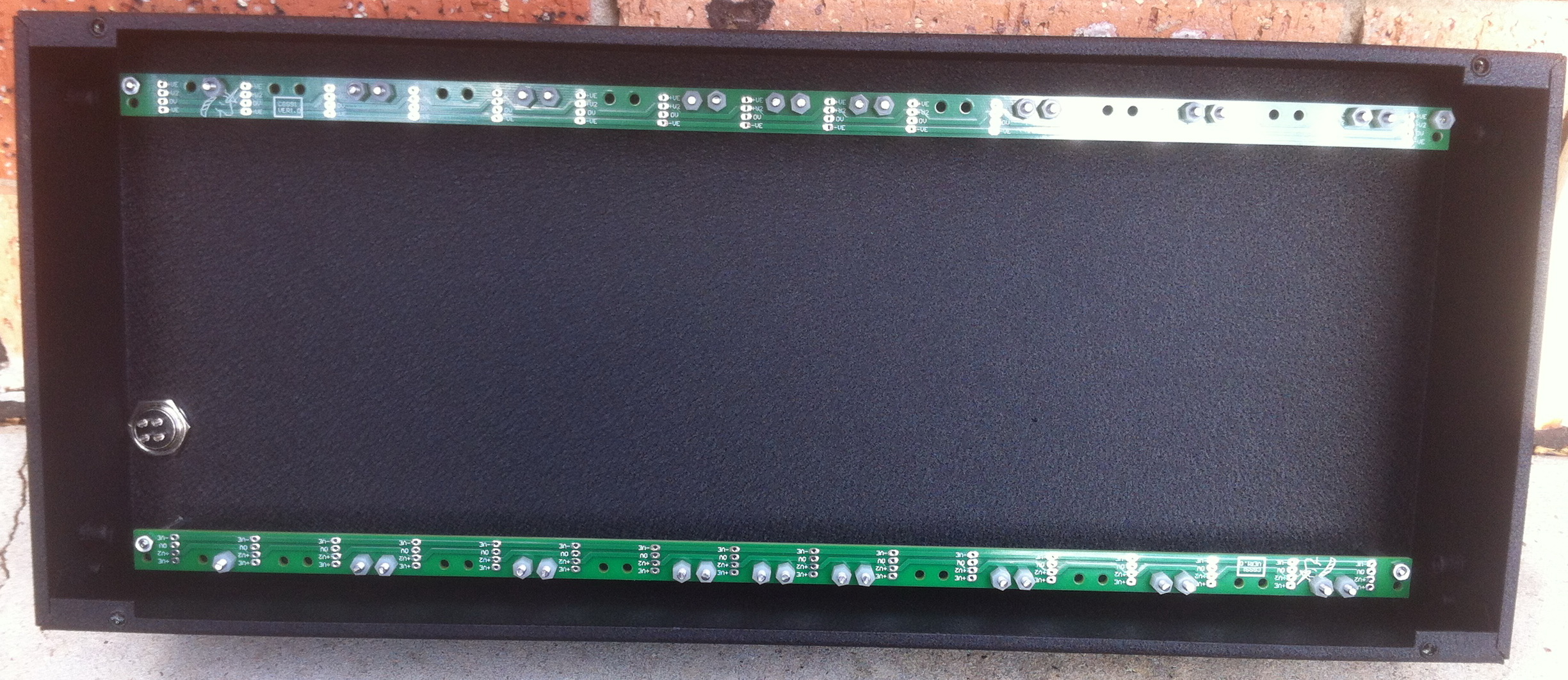
A pair of (earlier model) CGS391 boards mounted in our 4U Boat.
Mounted and loaded with bolts and spacers for (in this instance) the BOG PCB Set.
The CGS391 Power Rail boards are an alternate and recommended solution to getting power distributed to the boards in a boat. Initially designed to be mounted on the back of the front panel and to the allow the module boards to be mounted close to the panel components to ease wiring, they can also be mounted in the base of the boat providing a short route for power wires to the nearest set of terminals on the CGS391 rather than having to run long power cables around the boat to a CGS374 or similar power breakout board.
Minimal installation involves the power connections be hardwired direct from the power points on the CGS391 to the relevant power points on the module board. If this wiring is implemented sensibly along with the wiring to the panel components, it should be possible to tilt the module board over to get access to both the underside of the module board and to the panel component wiring for servicing etc. We recommend using the 4-way(*) power connectors on the module PCBs so that the PCBs can be removed if needed.
Some boats include a few modules that may cause interference on the power rails (such as designs involving a number of LEDs for example) and it may be found beneficial to mount these PCB’s in to the boat to use one of the CGS391 PCB’s as a power rail and using the other CGS391 PCB as a power rail for the other modules. This will then also allow for the inclusion of a simple filter from the power in connector to one (or both) CGS391 PCB(s). By also taking advantage of the fact that the power supply rail design allows for two 0V rails, one can be assigned to the lower CGS391 with the other assigned to the upper CGS391 PCB. In conjunction with 4-pin power connectors back to the main supply, it is possible to provide some separation between the power rails.
BOG PCB Set mounted on CGS391 PCBs
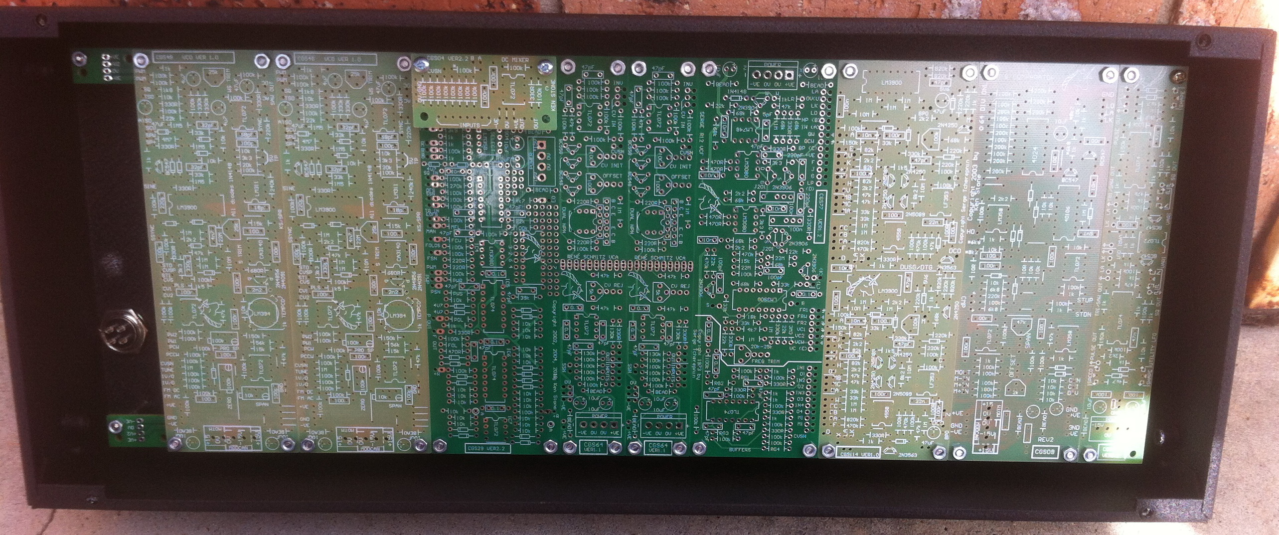
The following pages show pictures of an early SWAMP unit built in to one of our BUD enclosures and gives you an example of how the build may go.
NB: In this installation the distribution section on the CGS31 NOISE PCB have been used for power
Panel Details
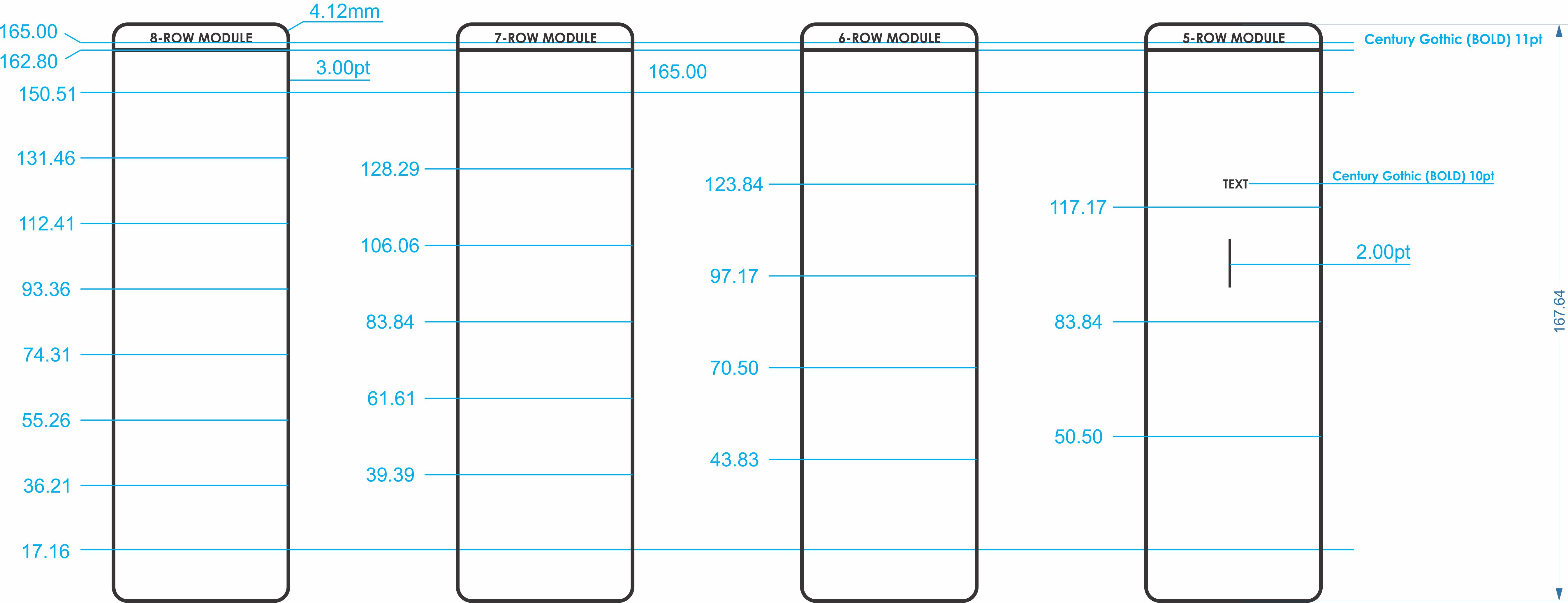
Panel Graphic Details
The above drawings shows details for the basic panel layout used for the BoCGS and Voltron families of 4U panels.
ELBY Design 4U Boats
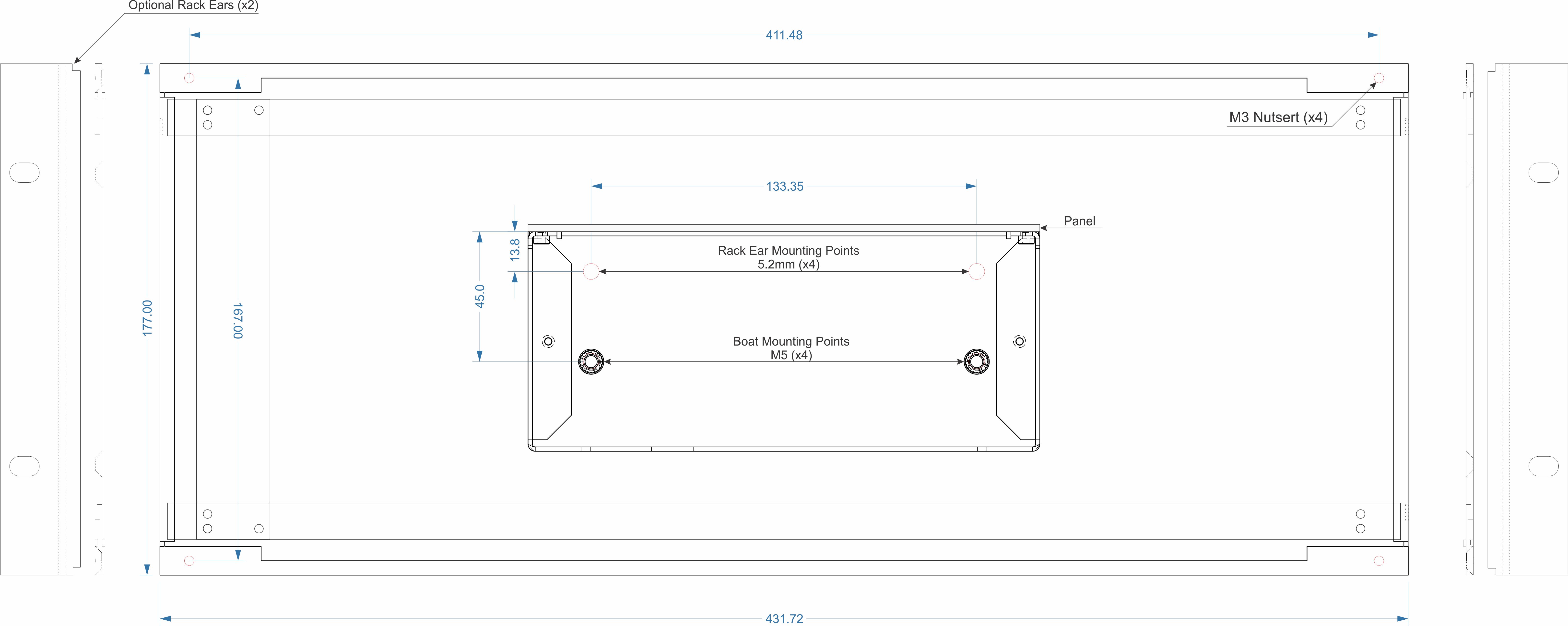
ELBY Designs 4U Boat Details
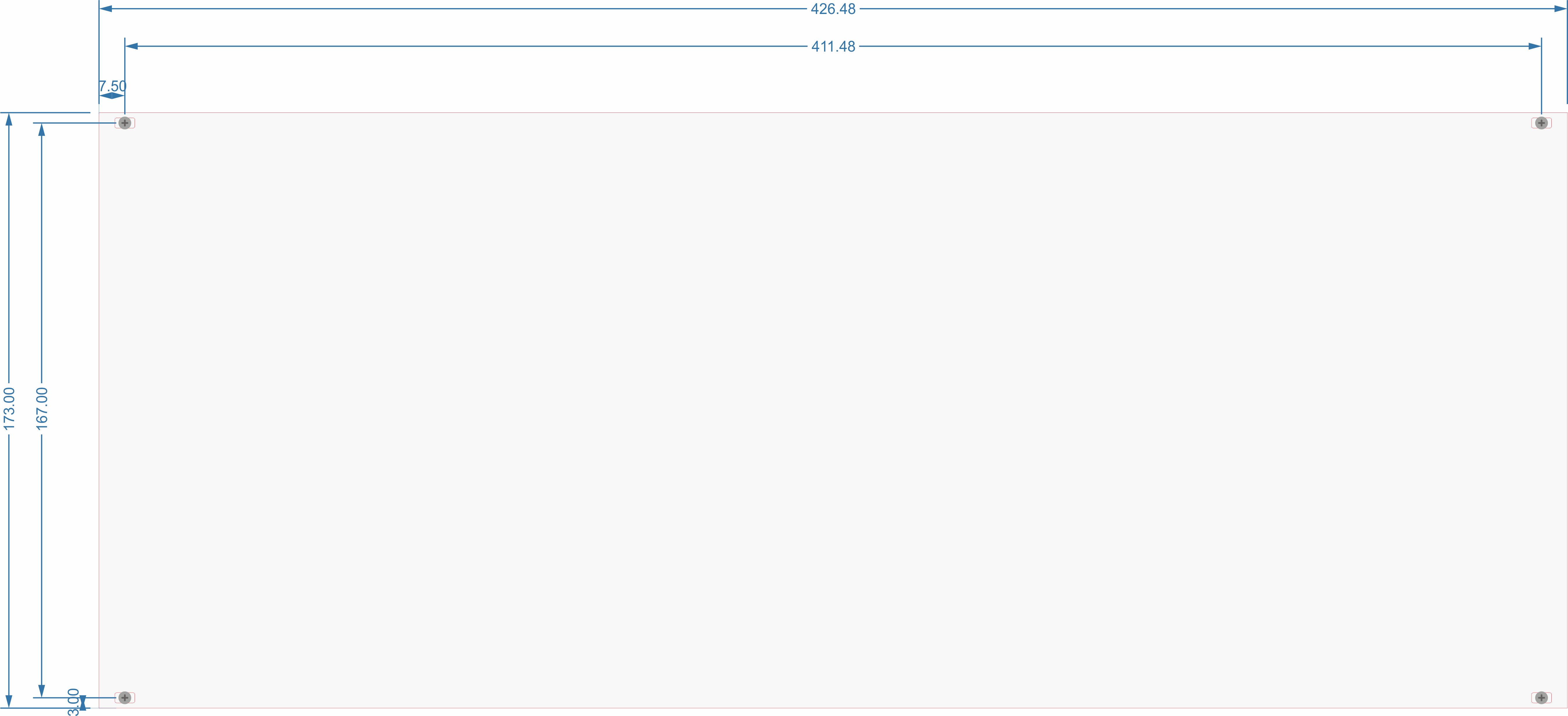
4U Panel Details
ELBY Designs 4U boats are a custom designed boat based on the BUD AC423. The design has been updated with the following features:-
• Integrated M3 nutserts for panel mounting
• Pre-drilled with mounting holes for a pair of CGS391Mounting Rails
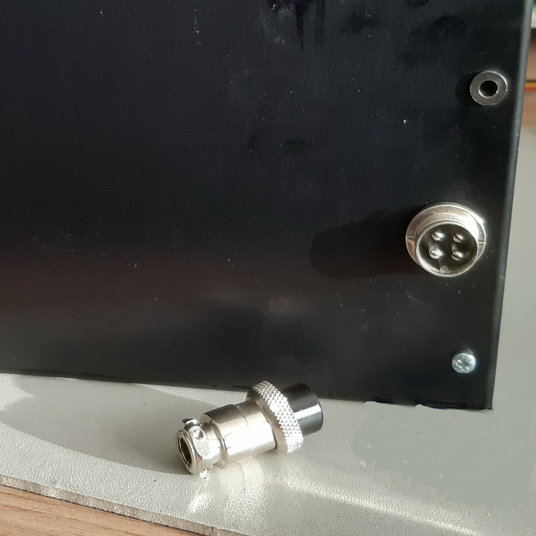
• Pre-drilled for a MIC power connector
• Pre-drilled for a 4mm uninsulated GROUNDING socket
• Black Satin anodized finish
• Reduced lips to provide better clearance for panel components
• Integrated M5 nutserts for mounting the boat in to custom enclosures
• Optional Rack Mounting Kit
Panel Components
The following table lists the common parts used on our BoCGS and Voltron panels.
Jacks |
|
Cliff S14 with an 8mm notched panel cutout |
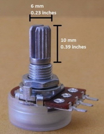
Pots |
|
Alpha RV16 pot with a 7mm panel cutout |
Switches - Toggle |
|
C&K 7000 Series with a 6.3mm panel cutout |
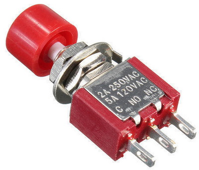
Switches - Pushbutton |
|
C&K 8000 Series with a 6.3mm panel cutout |
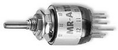
Switches - Rotary |
|
Nikkai MRA with a 6.35mm panel cutout |
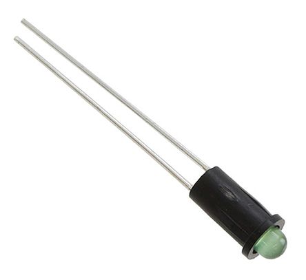
LEDs |
|
Dialight 558 series with a 4mm panel cutout |
Alternates parts may be used if desired but may require an adjustment of panel cutouts. Be aware that when substituting large parts of the clearance around the body of the component and other surrounding components.
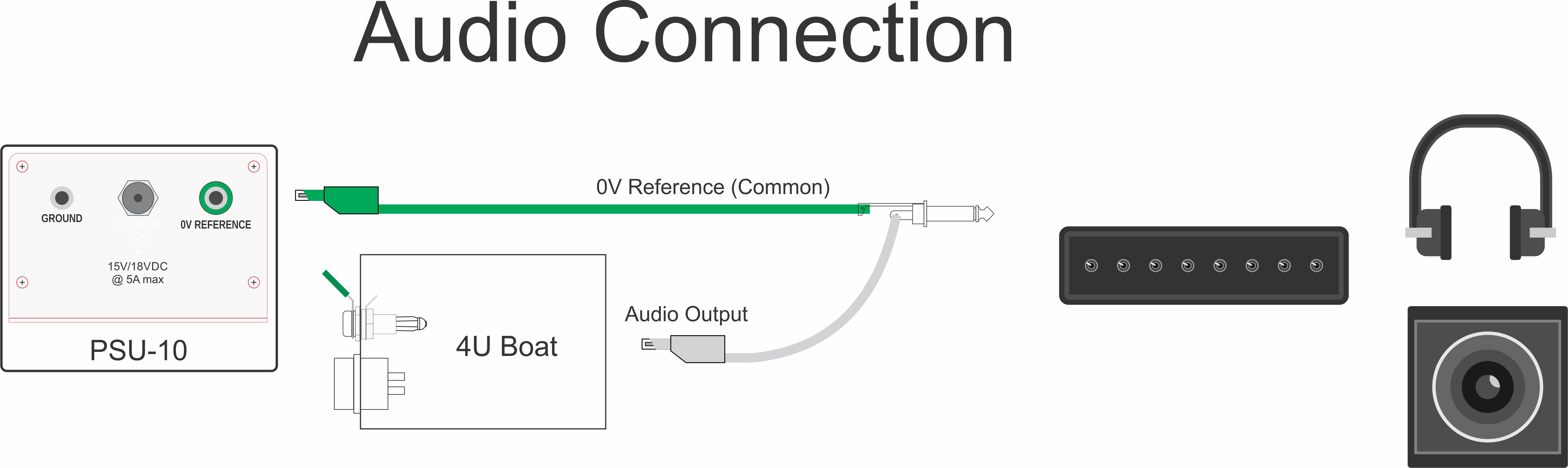
Connecting your 4U System to an external mixer/amplifier
If your 4U configuration does not include an ‘audio interface’ such as the MCSM in the Voltron 7 then you will need to consider how you can safely connect an output from your system.
There are 3 main issues to address:-
1) Signal levels in your 4U system will be ‘hot’ and so too large to be connected to most inputs on mixers and amplifiers
2) Banana jacks do not have an integrated 0V Reference which is needed to allow the external equipment to properly handle the signal from your system
3) Banana jacks are not commonly used on most mixer/amplifiers so an adaptor would be needed.
All of these issues are handled by the MCSM in the Voltron 7.
A relatively simple solution would be to assign an output on a VCA as an ‘AUDIO OUT’ and replace its banana jack with a 3.5mm jack. This jack would address issue (2) and (3) and require a 3.5mm to 6.35mm cable (preferably MONO although STEREO cables will often work).
Issue (1) could be resolved by building a simple passive attenuator on to the back of the 3.5mm jack. This would comprise 2 resistors selected to give a suitable attenuation and wired on to the back of the jack. The value of these resistors would be dependent on what equipment you are plugging in to and the specification of that instruments inputs. An attenuation ration of around 20:1 would be recommended as a starting point but this could be reduced if you find that the equipment has the ability to handle ‘hotter’ signals. This solution is, by its design, a fixed attenuator and you may find that some of your patches in your 4U system do not generate such hot signals resulting in weaker output levels with your equipment. If you have panel space for a pot then you could include this in the attenuator to give you control over the attenuation levels as needed.