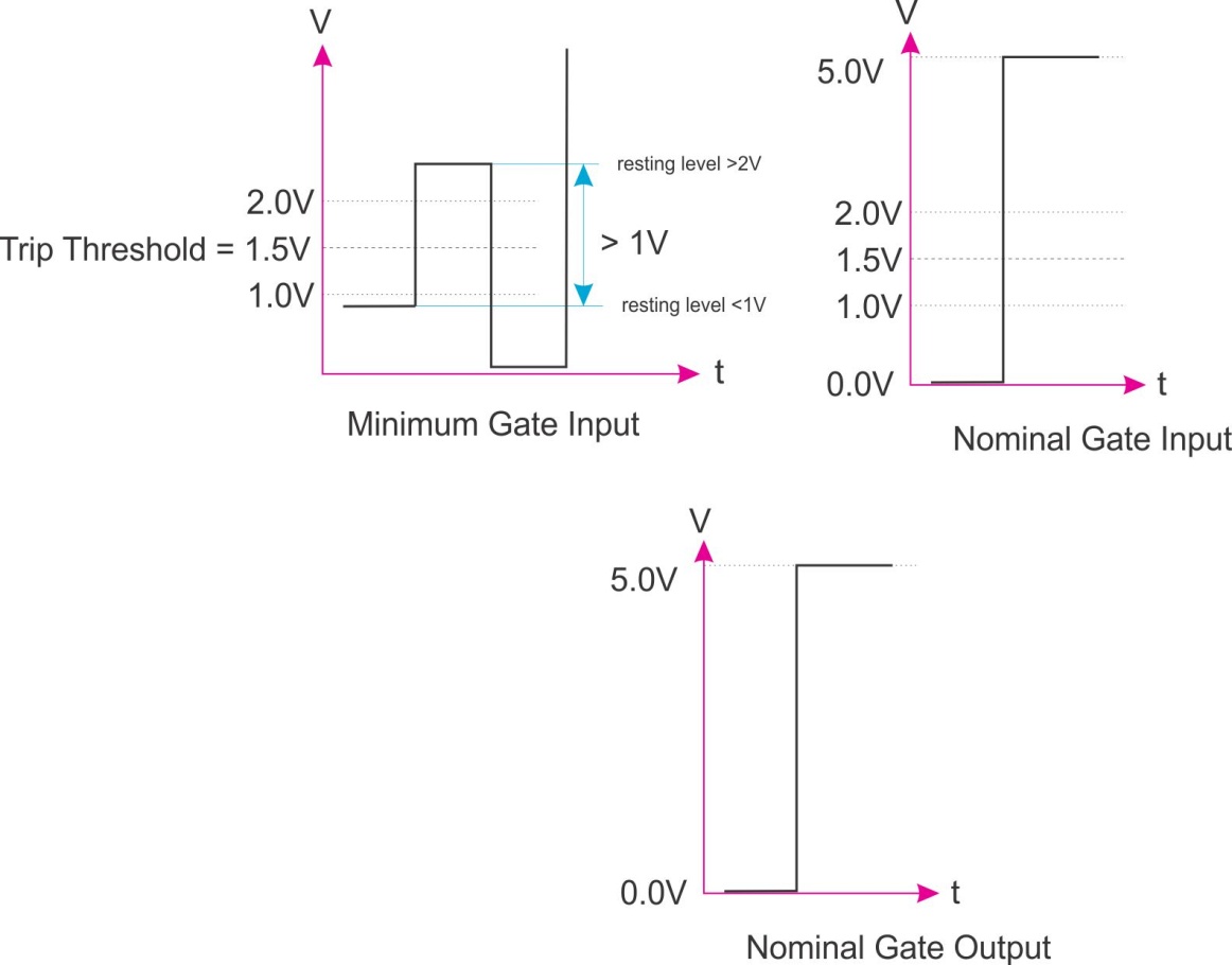
GATE Signals GATE signals have only 2 recognised states being:-
These states are defined by the 'resting' level of the GATE and not by its edge-transition. GATE IN (RED)
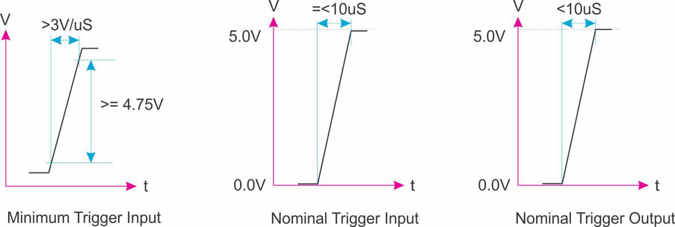
GATE OUT (YELLOW GATE OUT outputs will be 0V and +5V +/-1% GATE signals can extend in frequency from 0Hz to greater than 15kHz TRIGGER Signals TRIGGER signals are a variation of the GATE signal that depend on the edge-transition of the signal and not its 'resting' level. TRIGGER IN (RED)
TRIGGER OUT (YELLOW)
TRIGGER signals can extend in frequency from 0Hz to greater than 15kHz. A EuroRack Trigger is simply a GATE with a short 'ON' period, typically 1mS to 5mS. |
Email: elby-designs@bigpond.com
© Copyright 2000. All rights reserved. Revised: September 20, 2022


© Copyright 2000. All rights reserved. Revised: September 20, 2022