|
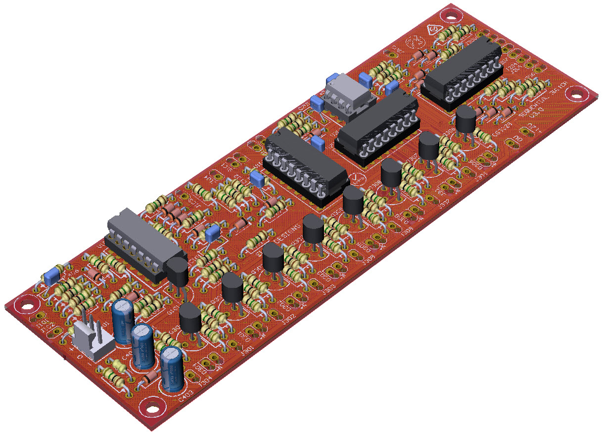
3D Model

|
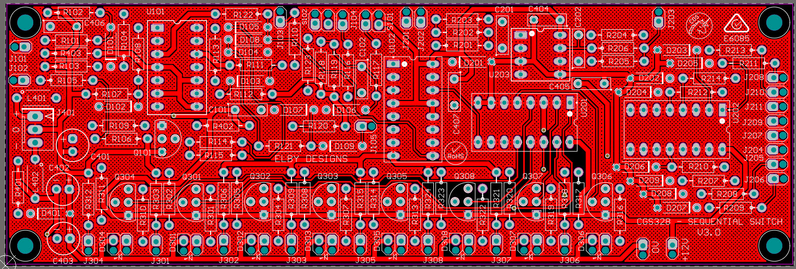
Overlay
|
PCB Plan View
|
Schematics
|
|
|
|
|
|
Constructors should refer to the Component Overlays along with,
the PCB Bill of Materials for the current value of all components, and
the General Construction Notes for general PCB assembly guidelines.
ADDENDUM
R124 - R127 are not on the PCB and need to be added as follows:-
- Solder R125 between U101_1 and the left leg of R122
- Solder R124 between U101_2 and the left leg of R122
- Solder R127 between U101_13 and the left leg of R122
- Solder R126 between U101_14 and the left leg of R122
A wire link also needs to be fitted betwwen U102_3 and U102_5
.


