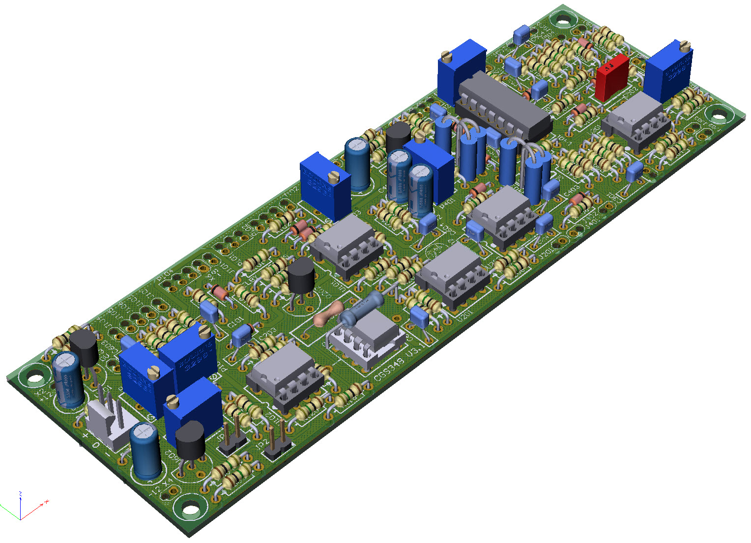
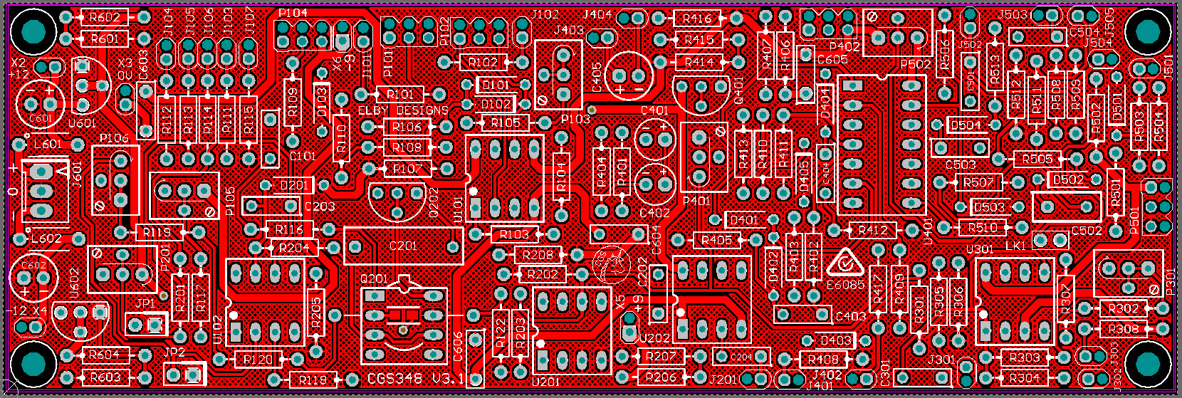
Constructors should refer to the Component Overlays along with,
the PCB Bill of Materials for the current value of all components, and
the General Construction Notes for general PCB assembly guidelines.
Modifications
The following modification provides a better match in the output levels of the [SINE] and [VARIABLE] waveshapes relative to those of the [SAW], [SQUARE] and [STAIRCASE] waveforms:-
- Mount R402 & R403 vertically in the lower pads of their footprint
- Mount R418 vertically in either of the upper pads of R402/R403
- Tie the 3 loose ends together and solder all parts
- Mount R410 & R411 vertically in the lower pads of their footprint
- Mount R419 vertically in either of the upper pads of R410/R411
- Tie the 3 loose ends together and solder all parts .


