|
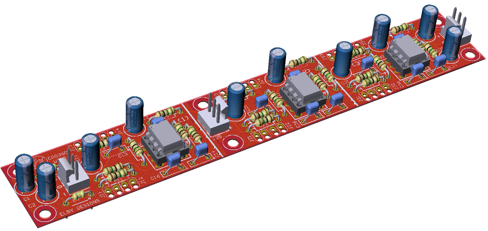
3D Model

|
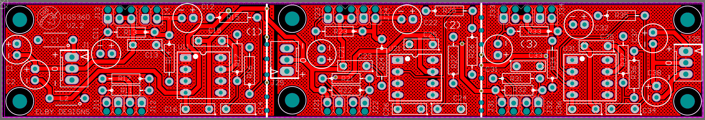
Overlay
|
Plan View
|
Schematics
|
|
|
|
|
|
Constructors should refer to the Component Overlays along with,
the PCB Bill of Materials for the current value of all components, and
the General Construction Notes for general PCB assembly guidelines.
The CGS360 PCB contains 3 separate sections each providing an ‘input’ section and an ‘output’ section. The PCB can be cut to allow the sections to be located individually or to remove unused sections. Carefully cut along the white separating lines using a fine hacksaw. Power connections for sections (2) and (3) are provided at J25 and J35 respectively if you need to use the removed sections.
The preamplifier of the stomp box adapter is a basic non-inverting amplifier with an AC gain of 20, and suppression capacitors as needed. The input impedance is approximately 150k.
The AC gain can be changed if needed by adjusting the values of R15/R12 for section 1, R25/R22 for section 2 or R35/R32 for section 3 - see table below for examples
GAIN |
Output
Section 1
- R15
Section 2 - R25
Section 3 - R35
|
Input
Section 1 -
R12
Section 2 - R22
Section 3 - R32
|
|
5 |
|
10 |
|
20 |
|


