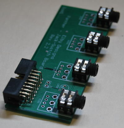
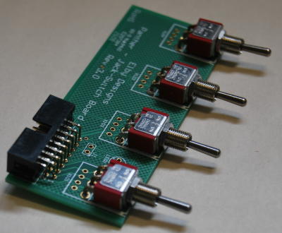
To help minimize the amount of wiring that is often needed to connect panel mounted components to the circuit board the Panther family make extensive use of Panther Support Boards. There are, currently, 5 members of this family:- 1. Panther Jack-Switch Board Panther Jack-Switch and Jack-LED Board These boards can support any mix of up to 4 jacks and switches. The 2 pictures below show the boards dressed with 4 jacks and the other with 4 switches but any permutation of these is allowed. These PCBs are used when the associated front panel column has only jacks and/or switches.
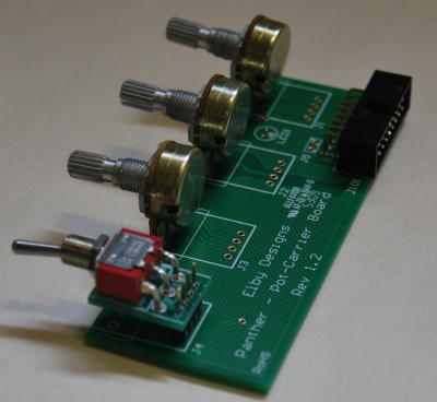
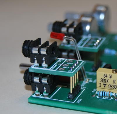
While the Jack-Switch board will accept a single LED in one of 3 positions, the Jack-LED will accept up to 4 LEDs and has 7 different positions for them (2 different positions for the 'top' 3 LEDs and one position for the 'bottom' LED. Panther Pot Board This board supports pots and, optionally, a mix of jacks and switches. When adding jacks or switches to this board they will (nearly) always be done by mounting them using the Panther Carrier Board. The picture shows this board with 3 pots and a switch. This PCB is used whenever the associated front panel column comprises a mix of pots, jacks and/or switches and requires the use of a Carrier PCB for each jack/switch to allow them to be aligned with the centre of the pots.
Panther Pot loaded with pots and a switch Panther Support-5 This Support board provides for a an alternate panel grid layout that now provides for 5 components vertically in a column. It is a multi-component board accepting a variety of combinations of pots, jacks and switches. Panther Carrier Board To allow components on the front panel to be aligned vertically within a column, it is necessary to raise the lower height components such as jacks and switches. This is achieved by mounting the component on to a carrier board which is then held at the correct height using an extended header. Two header heights are used in the Panther modules:-
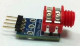
Occassionaly a design allows the main PCB to be mounted directly behind the front panel without using any Panther Support PCBs, for example our ED701 and ED702. To allow continued used of our jacks in these designs we use a mini-Carrier PCB
|


© Copyright 2000. All rights reserved. Revised: December 9, 2023