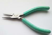
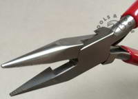
PCB Components Most components in the kits we supply are designed to be mounted directly on to the board requiring only minimal pre-forming in some cases (mainly resistors and diodes). If, however, a component is supplied or used that does not match the footprint on the pcb then you will, of course, need to form the legs so that the component can be fitted. A pair of small snipe-nose pliers should, ideally, be used for this task. The leg to be formed should be held by the pliers at a point immediately before the position the bend is to be made (i.e. the pliers will be holding the leg on the side nearest to the component body). Using your fingers or another pair of pliers or suitable tool, bend the leg to the desired angle. For axial resistors this would typically be 90º. Sometimes a component such as a tantalum capacitor may be supplied, for example, with 0.1” pitched legs but needs to be fitted in to a 0.2” footprint. In these cases you should form both legs as described above. As always, pay careful attention to minimize the stress on the junction between the leg and the body of the component. Panel Components
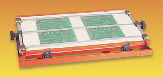
Installing components (PCB dressing) It is recommended that you install components by height starting with the smallest components (wire links and diodes) first and gradually building up to the tallest components. Do not try to fit too many components at the same time otherwise you may have difficulty accessing the solder points on the components, this is more specifically true for components with long legs such as resistors and capacitors. Although not essential to the operation of the unit, it is desirable to keep components flat to the board (unless the design specifically requires a component to be mounted `off the board’). For long legged components we suggest bending the legs at an angle after they have been inserted in the board. An angle of around 45° is fine as it still allows the component to be removed fairly easily should the need arise. An alternative method is to temporarily hold the components to the board using a low-tack tape. A few components are positioned on the board and then a strip of tape is laid over them, flip the board over and solder. A solution for when you intend to build a number of boards is to get a piece of, about, ½” foam about the same size at the board you are going to work on. Glue a piece of stiff card on to one face of the foam. Rest your PCB on some support so that the long components legs can protrude through the PCB without hitting anything. When you have placed a number of components, lower the foam on to the PCB (foam side down). Grasp the PCB and foam at each end and flip them over placing it on a flat surface. Carefully tack one leg of each component and once done, flip the PCB over and check that all components are sitting flush to the board. Flip the board back and solder all the remaining joints making sure you reflow the `tacked joint’ last to ensure that it has soldered properly. It is crucial with this method that you adhere to the lowest to highest rule here otherwise you will find components end up standing off the board. If you intend to do large amount of PCB assembly then it is worth investing in a pcb assembly jig such as that shown here.
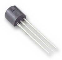
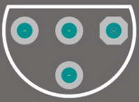
This works on the same principle as the foam option above but uses a clamp mechanism to hold the foam firmly against the board. Vias These are the little solder pads with no legend that seem to attach to no component. They allow copper tracks to swap sides on the circuit board. There is no need to fill these with solder and in the case of most of ELBY Design boards this is not possible because they are tented (i.e. they have a coating of solder-mask over them) to prevent liquids such as solder getting in to the hole, as well as providing a solid surface over the holes for any silkscreen printing and ensure that the printing remain legible. Mounting Transistors, Diodes, Capacitors, Trimpots and ICs For TO-92 Transistors match the flat side of the device with that shown on the PCB legend. Push the transistor into place but don’t push too far. Leave about 0.2” (5mm) of the leads visible underneath the body of transistor. Turn the board over and slightly cinch the two outer leads on the flip side, you can leave the middle one alone. Now solder the middle pin first, then the other two pins.
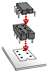
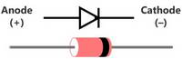
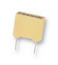
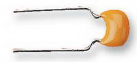
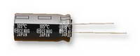
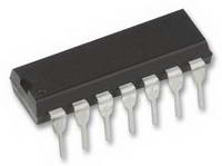
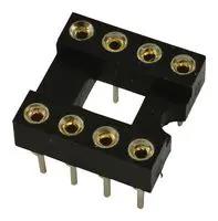
The TO-92 footprint has an extra 'centre pad' which can be used for transistors that have a staggered (triangular) formation of the legs. You can also use this pad instead of the 'centre inline' pad for inline formed legs if preferred. Diodes can be treated much like the resistors. However, they must go in the right way. The cathode is marked with a band on the body of the device. This must align with the vertical band on the board. Polyester Capacitors are like little blue, yellow or red boxes. Push the part into place up to the board’s surface. Little lugs are sometimes incorporated in to the body to leave enough of an air gap for any flux wash to work. Cinch and solder the leads as you would resistors. Ceramic Capacitors need to be treated with a little respect. Don't bend them to much once you have soldered them in. Do trim down the leads with wire cutters, even if they don't have that much to chop off. Electrolytic Capacitors are polarised, and may explode if put in the wrong way. Oddly, the PCB legend marks the positive side with a ‘+’, although most capacitors have the ‘-’ marked with a stripe. Obviously, the side marked with a ‘-’ must go in the opposite hole to the one marked with the ‘+’ sign. Most capacitors usually have a long lead to depict the positive end as well. Most ICs have a mark or indentation in the moulding indicating the end at which pin 1 is. Another general rule-of-thumb is that the labelling on the top of the IC is legible left-to-right when pin 1 is at the lower left corner. We strongly recommend the use of IC sockets with machine turned socket-pins
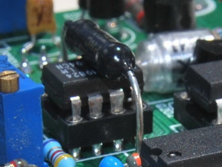
Trimpots are available with either an inline footprint or with the centre-pin offset to one side. You should not bend the leads of these devices, the standard parts will fit in one or the other footprint without issue. The silk-screen has a circle identifying the end to which the trimmer should be located. Once all the components have been mounted and soldered you should check that all the legs are neatly trimmed to a maximum of 2mm. Give the board a good clean with a PCB cleaner compatible with the solder flux that has been used. This is mainly to remove all excess flux which, if left, may eventually start to erode at the board and components. Tempco's Tempcos usually need to be mounted in close thermal contact with a main component on a board. The picture below shows a PT146 style Tempco mounted across an IC using the pcb footprint below.
A small amount of heatsink compound can be applied between the body of the IC and the Tempco to improve thermal bonding. The following notes apply to our 3U family of designs
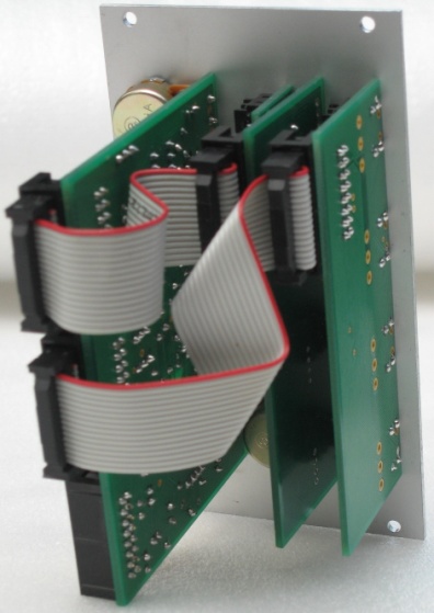
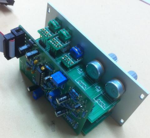
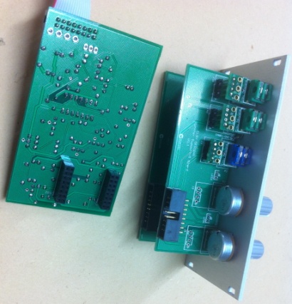
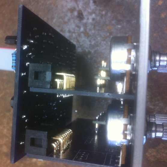
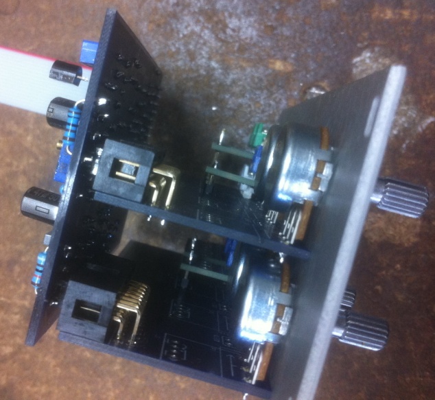
None of our Panther boards include mounting points making them harder to use in DIY builds that do not utilise our Panther Support boards or, where applicable, the onboard PCB-mounted panel components. IDC Receptacle Sockets When mating the back board of a module on to the front panel support boards, it is important to check for the correct alignment of the IDC Receptacle in to its mating IDC Headers.
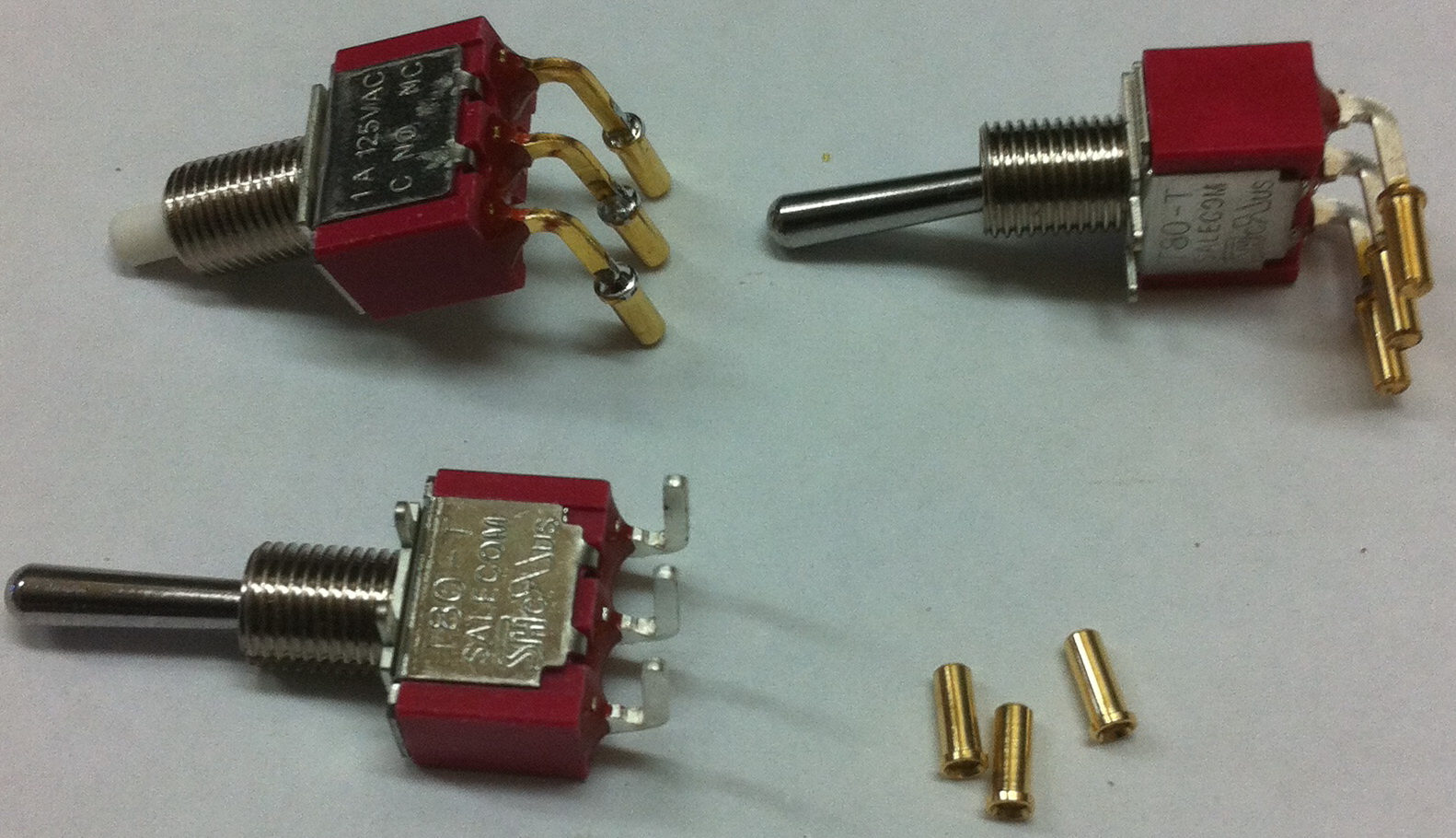
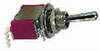
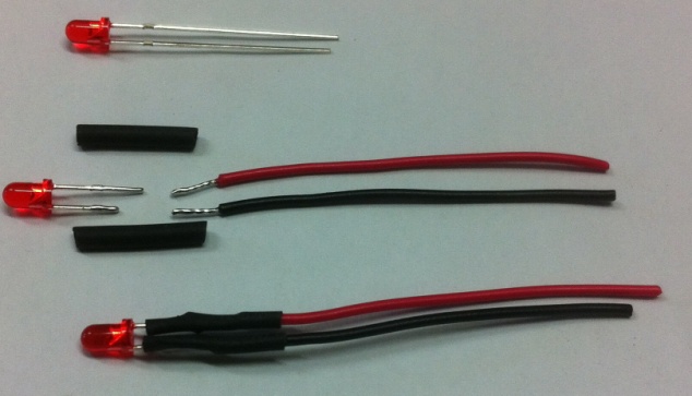
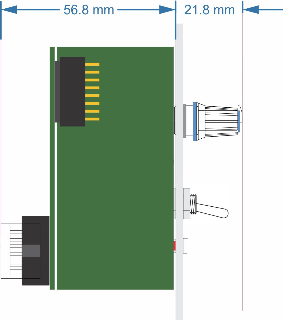
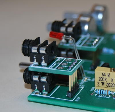
It is important to check both ends of the connectors. Mounting LEDs Where possible, PCB designs allow for an LED to be directly mounted to the PCB. We recommend pre-forming the legs to reduce stress on the LED body and to provide some flexibility in the mounting after the LED has been soldered in to place. In some PCB designs the LED has to be positioned further back from the panel and it may not be possible to fit the LED due to the legs not being long enough. In these cases we supply 2 pieces of wire and heatshrink to create 'extended legs' (see earlier notes regarding assembly). Mounting Switches When mounting switches on to any of the Panther boards you should fit one nut to the switch before mounting on to the PCB. Once mouted to the Front Panel, use the 2nd nut to secure the switch, make sure that the long face of thew switch body is parallel to the edge of the panel to ensure that the toggle action is near vertical. The body of the switch should then be adjusted to be parallel to the PCB. When mounting single-pole switches directly to any of our boards other than a Carrier board, you should endeavour to finish with the component legs flush with the solder side of the board To allow for proper vertical alignment of components in columns we will often use a Carrier PCB which is mounted on to header pins. This allows for fine adjustment of the component above the main PCB allowing it to correctly align with its panel mounting hole.
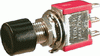
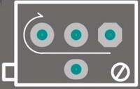
This picture shows a jack mounted on to a Carrier PCB, itself mounted onto a header to allow for vertical height adjustment. The same Carrier PCB will also allow for single-pole switches to be installed this way. For multi-pole switches we have other dedicated Carrier PCBs. Mounting the Pots The first thing to do is to check your pot values. Different manufacturers use different coding methods to define the `law’ of the pot. ALPHA pots use the following:-
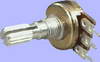
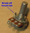
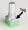
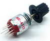
So, for example, a 100K Logarithmic pot from ALPHA will be marked 100KA whilst a 50K Linear pot will be 50KB. Next, most pots have an anti-rotation tab which is intended to locate in to a mating hole on the front panel, see earlier notes about removing these. Fit each pot into the appropriate holes in the PCB. Lightly solder the center pin of the pot leaving the other two pins. Now check if the pot is standing square to the PCB. If it is not, simply reheat the soldered pad to allow you to move the pot into the correct position. Don’t leave your iron in contact with the pad for too long as this will lift the pad and could also damage the pot by getting too hot. When you are happy with the location, you can solder the other two pins of the pot. We recommend trimming the centre leg to about 1mm above the PCB to prevent possible contact with adjacent components when used on our Panther Support Boards. |


© Copyright 2000. All rights reserved. Revised: September 23, 2024