General Construction Notes

Component PCB Footprints (2)

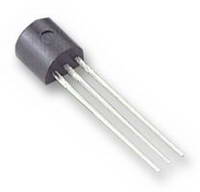
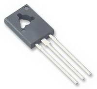
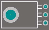
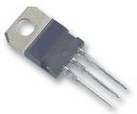
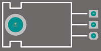
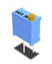
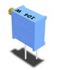
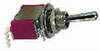
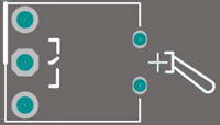
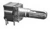
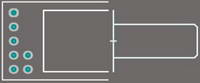
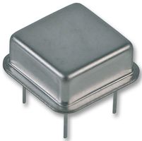
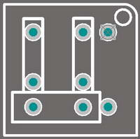
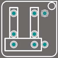
The following tables show typical PCB footprints used on ELBY Design PCBs. They are 'typical' as there will always be varaints in some components eg electrolytic and tantalum capacitors come in a variety of body sizes and, occasionally different pitches, and this will result in small differences in the footprint

Transistor
TO92
Transistor
TO126
Typically folded over and layed flat to the PCB
Transistor
TO220
Typically folded over and layed flat to the PCB
Trimpot
Vertical Adjust
Trimpot
Horizontal Adjust
Switch - Single-pole, Toggle
Switch - Single-pole Pushbutton
Switch - Rotary
1-pole 3-way
to
1-pole 6-way
Crystal Oscillator (DIP)
Some early PCBs had this footprint with the body outline incorrect.
The 'dot' correctly indicates Pin 1
Crystal Oscillator (DIP)
This corrected body outline still has the 'dot' correctly identifying Pin1
Email:  elby-designs@bigpond.com
© Copyright 2000. All rights reserved.     Revised: December 9, 2023