The Doepfer A-100 system uses a 16-pin IDC connector with the following pin assignment:-
The main issues with these assignments are:-
The specification changes are as follows and simply involve removing
the +5V and CV/GATE lines from the Power Bus and enhancing the
definition of the main power rails:-
Busboard designs should aim to achieve an absolute maximum impedance for all power rails of 10milliOhm. This measurement is for any power terminal on a module to its source at the main power supply connection and so includes modules power cables and any busboard-busboard and busboard-power supply connections. Many EuroRack modules currently use a 10-pin IDC connector as these modules do not require accesws to the CV/GATE buss and either do not require a +5V power rail or generate it internally. The change of busboards to usinga 10-pin IDC header instead of the standard 16-pin header only really impacts the EuroRack market in that the user would need to change the module power cables. For those modules requiring access to the CV/GATE signals it is proposed that a separate 'DATA/CV/GATE' bus be implemented, and those few modules requiring an external +5V power rail, the inclusion of an inline adaptor is a suggested solution.
The basic arrangement of the power pins remains the same as that for EuroRack so any EuroRack module can be fitted in to a EuroSynth system although it will require either a 16-pin to 10-pin power cable or a 10-pin to 10-pin power cable. Normal IDC ribbon cables with an insertion-displacement mechanism can also be used if desired. Mains Earth Grounding (*)
Chassis Ground (*) Chassis Ground is to be used solely for providing a ‘ground’ connection for the metalwork in a system and for screen connections and should not be connected to 0V accept at the designated point. Panel mounted components that have a leg (or legs) that will be connected to the chassis when installed, must not have a PCB connection to the modules 0V rail. The EuroSynth specification does not recognise 5V as a standard power rail and so has removed it from the power system. Any EuroRack module that requires an external 5V rail will need to use an inline 12V-to-5V adaptor such as the EURO-5V. It is also possible to use a -12V-to-5V adaptor given that the adaptor pays due attention to emissions and does not pollute the -12V rail with switching noise. CV/GATE Bus Few modules, currently, utilise the CV/GATE pins. Also, the single CV/GATE pairing is only really beneficial in a single-voice/monophonic system. As such, EuroSynth is dropping these pins from the power bus. A separate 'DATA BUS' will be defined later. Power Rail Specification Both the +12V and -12V should meet the following criteria:
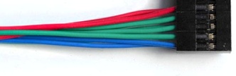
All module cables must assign pin 1 of the IDC socket to electrical pin 1 (i.e. -12V) to ensure correct orientation of module power cables. All modules and busboards should use 10-pin boxed headers to ensure correct orientation of module power cables. To promote a more integrated system permitting easier mixing of products from different manufacturers the proposal recommends that all power-to-busboard and busboard-to-busboard connections be made via 1/4" quick-connect terminals. NOTE: Removal of the +5V rail and CV/GATE still allows existing busboards to continue to be used. EuroSynth modules use a 10-pin header so just need to use a 10/16-pin IDC cable (which is already a common part in EuroRack) or a 10/10-pin IDC cable. (*) The information given here is for guidance only. Manufacturers/designers must employ suitably qualified personnel (eg fully licensed electricians) to ensure that the final equipment is fully compliant with the relevant electrical health and safety regulations for the country of use. This may involve submitting the equipment for safety testing. |


© Copyright 2000. All rights reserved. Revised: August 29, 2023