Signals can be generally broken in to 3 main categories:-
The correct way to specify signals is:-
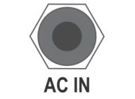
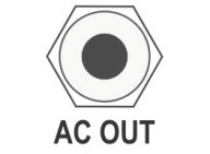
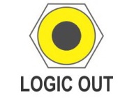
The specification will further split each signal category in to an INPUT and an OUTPUT specification. Colour Coding EuroSynth proposes defining an input/output colour coding scheme to assist with easier/faster identification of an input/output jacks function. This will be, of course, a purely optional specification but products using the colour scheme will promote a more user-friendly interface. The scheme is divided in to the 3 signal categories AC/Audio, CV, Logic (GATE and TRIGGER). Each category is further sub-divided in to IN (3-colour), OUT (6-colour) and SPECIAL (9-colour) Users of 4U SERGE Systems will recognise that the INPUT colour coding remains the same as specified by SERGE. It is STRONGLY recommended that the 6-colour system be adopted as a minium to allow for easy differentiation of input and output signals within each category. The 3rd column for the 9-colour system is somewhat optional as these are rarely used. Patch Points The EuroSynth specification advocates the use of 4mm banana jacks as the preferred patching connection. These offer a larger contact surface between the plug and socket and provide a more robust connection.
NB: CV Signal Rational The following notes should be read to help explain some of the logic behind the levels specified here. VCAs can be scaled to at least 12dB per Volt. This helps provide the best sounding envelopes, 5Volt peak providing a meaty 60dB envelope sound, including total shutout at 0Volt VC. A single-turn pot can do a good job of tuning over 5 octaves. Tuning accurately over 8 octaves or more can start to be a problem with a single-turn pot. INPUT/OUTPUT Impedances To maintain maximum compatibility between modules and to minimise signal drops, it is important to define recommended input and output impedances. In general, EuroRack uses 1K for output impedance and 100K for input impedance. Although 1K is workable for many signal levels, it is desirable to have a lower figure for sensitive CV inputs like the 1V/Octave input/output. EuroSynth recommends for sensitive CV outputs (1V/Octave for example) that the impedance be around 50R while other outputs can be around 330R. Input impedances should, typically, be in the region of 100K with a lower limit of 47K. NOTES: All of the above levels have been selected as they allow for the use of unshielded patchcords and help avoid high-frequency pollution with low-impedances outputs which are less capable of being absorbed than at medium and lower frequencies. When defining these signal levels for the EuroSynth a number of considerations where looked at including:-
|
© Copyright 2000. All rights reserved. Revised: September 20, 2022
