|
3D Model |
Overlay |
Plan View |
Column 1 PCB |
|
|
|
Column 2 & Column 3 PCB |
|
|
|
ES21 PCB |
|
|
|
ES21 Chicklet PCB |
|
|
|
Constructors should refer to the Component Overlays along with,
the Bill of Materials for the current value of all components, and
the General Construction Notes for general PCB assembly guidelines.
- Start by preparing the 10x LEDs as per the instructions in the General Construction Notes
- Fit all components to the boards following normal assembly guidelines excluding the 10x LEDs, MANUAL pushbutton switch, R105, R106 and R107
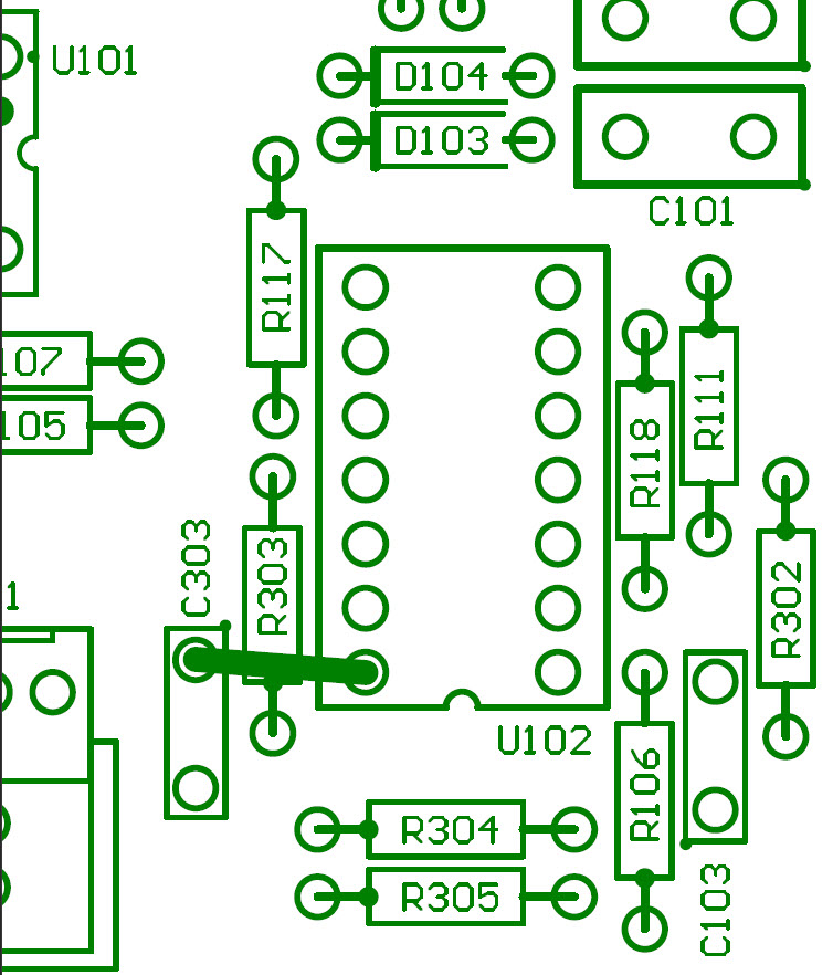
- Fit a wire link between U102_14 and C303_1 on the ES21 PCB variant 2
- Fit the Column 2 assembly to the front panel
- Mount 5x LEDs ensuring the correct orientation of the LED wires in to the board and solder in to place
- Remove the assembly and repeat for the Column 3 assembly
- Mount the pushbutton switch on to the Column 1 assembly but do not solder
- Offer the assembly up to the front panel and secure using the supplied nuts and then solder in to place
- Mount the other assemblies on to the front panel and secure in to place
- Fit the back-board assembly ensuring the correct alignment of the IDC Receptacles in to their respective sockets
Addendum
On the V0.1 revision of the ES21 Support Board, the pad for J6_4 has been cut and should not be soldered to the connector.

