|
3D Model |
Overlay |
Plan View |
Column 1 - Column 4 PCB |
|
|
|
Backboard PCB |
|
|
|
Constructors should refer to the Component Overlays along with,
the Bill of Materials for the current value of all components, and
the General Construction Notes for general PCB assembly guidelines.
- Assemble 4x Jack Carrier Boards
- Assemble 4x Switch Carrier Boards
- Prepare the 4x D103 LEDs as per the instructions given below
- Prepare 4x toggle switches and 4x pushbutton switches by fitting ferrules
- Fit all components to the 4x ES24 Stage boards except for the sub-assemblies and LEDs
- Mount S102 and S103 on to one of the ES24 assemblies but do not solder
- Offer up to the front panel and secure with a single nut on the central pot and a nut on the jack
- Secure S102 and S103
- Flip the board over and trim the ferrules to near flush with the PCB
- Solder the ferrules in to place
- Remove the assembly and repeat for the remaining 3x assemblies
- Starting with 'Stage 1', mount the J102 and S101 sub-assemblies but do not solder
- Offer the assembly up to the front panel and secure using the appropriate nuts
- Ensure that the toggle action of S101 is vertical and then solder the sub-assemblies in to place
- Install the LED assembly
- Repeat for the remaining 3 columns
- Assemble the Back Board and mount on to the column boards ensuring correct alignment of the IDC connectors
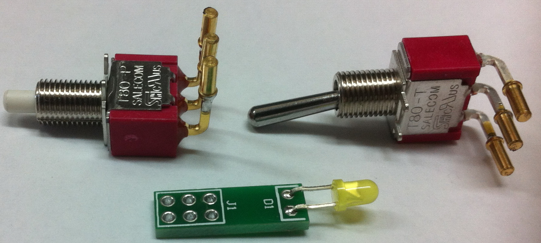
Preparing D103
A) Using our LED Carrier PCB
- Form the legs of the LED to 90 degrees approximately 5mm from the body
- Take care to note the orientation of the LED with respect to the main PCB
- Solder the LED in to the D1 position on the LED Carrier PCB
B) Using equipment wire
Follow the instructions as per our General Construction Notes