|
3D Model |
Overlay |
Plan View |
Column 1 PCB |
|
|
|
Column 2 PCB |
|
|
|
ES30 PCB |
|
|
|
ES31 PCB |
|
|
|
ASM306 Support PCB |
|
|
|
Constructors should refer to the Component Overlays along with,
the Bill of Materials for the current value of all components, and
the General Construction Notes for general PCB assembly guidelines.
Start assembly by following the ES30 Build Guide
-
Install the ES30 as per the guide
With the ES30 section built you can move on to the final construction stage for Column 3.
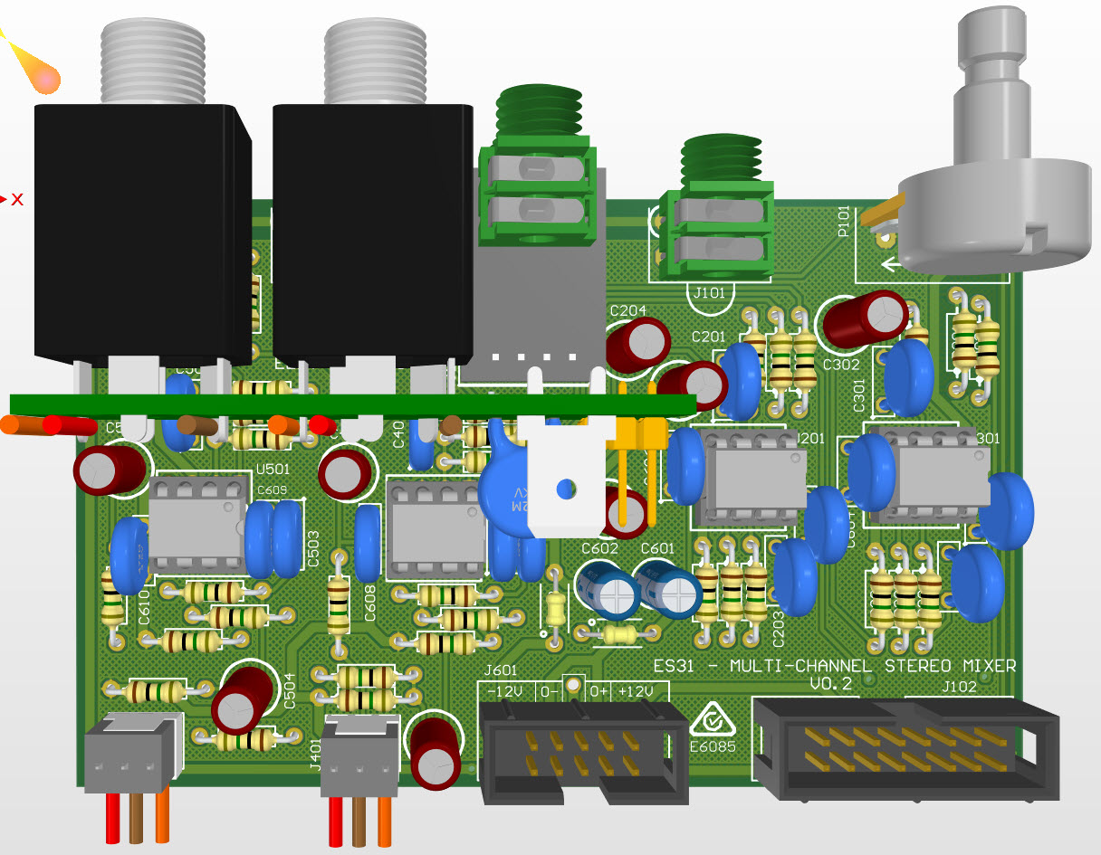
- Assemble the J203 Carrier Jack Board assembly (3D Model)
- Fit all components to the main board following normal assembly guidelines except the J203 sub-assembly
- Mount the sub-assembly and offer up to the front panel and secure using the supplied nuts
- If not already done, remove the 3rd section (J7) of the ASM306 Support Board - use a pair of strong side pliers or a small hacksaw
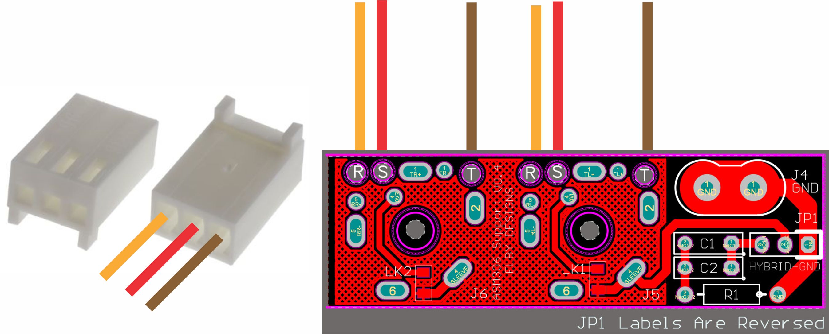
- Solder wires to the 6 points on the Support Board, using the associated anchor points to hold the wires secure - see Figure 1
- Fit the remaining components excluding the 2x jacks. When fitting R1, fold its right-hand leg under and solder to the right-hand pad of C2
- Fit a wire link from the 0V pad of J3 to the left-hand pad of R1 as shown in the overlay
- Loosely mount the 2x jacks on to the front panel, checking that the slanted corner of each jack is furthest from the nearest edge of the panel and that the jack bush is properly located in the panel
- Offer up the Support Board, tighten the nuts on the jacks and then solder the Support PCB in to place
- Cut the wires for J401 to the same length and then strip approximately 3mm off each wire and attach the crimps
- Repeat for J501
- Fit the crimped wires in to the 2x MTA housings and connect to their respective headers on the main board as shown here


