There are 3 adjustments that can be made on the MIDI-Retrofit-8.
To allow calibration for steps (2) and (3) it is necessary to have a MIDI controller connected and for the MIDI-Retrofit-8 to respond to that controller. If your MIDI controller cannot be set to generate MIDI Channel 10 messages then you will need to go through the [LEARN] Mode and set at least the assignment for [TRIGGER 1] using a channel that your controller uses.
If you require a positive-going trigger output then DIPSWITCH #1 should be set of OFF. If you will be using a negative-going trigger output then you should set DIPSWITCH #1 to ON.
(1) This adjustment is used to set the lower voltage level of the output trigger pulse
-
Set dipswitches 2, 3 & 4 to the OFF position.
-
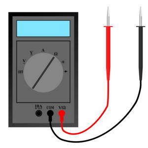
Monitor the output of TRIGGER 1 with a multimeter and adjust P301 to set the ‘OFF’ trigger pulse voltage to the desired level, typically 0V/5V.
(2) This adjustment is used to set the higher voltage level of the output trigger pulse
-
Set DIPSWITCH #2 to ON
-
Connect a MIDI Controller to the MIDI IN socket
-
Press and hold the note corresponding to [TRIGGER 1]. The note must have a MIDI Velocity >= 120
-
Monitor the output of [TRIGGER 1] and adjust P401 to set the ‘ON’ trigger pulse voltage to the desired level, typically 5V/0V.
(3) This adjustment defines the pulse-width of the TRIGGER outputs. This should be set to the smallest time period possible consistent with reliable triggering and operation of the attached triggered devices. If the pulse is set too small then some triggered devices may not trigger reliably or some devices may not produce the full `sound’ for which they were designed. Increasing the pulse-width over the optimum period will affect the speed at which MIDI-Retrofit-8 can accept repetitive triggers for the same output. If you do not know the optimal pulse width for your applications we suggest setting it to around 1mS
-
Monitor the output of [TRIGGER 1] with an oscilloscope
-
Repeatedly play the assigned note
-
Adjust P101 to set the desired pulse width.
Your unit should now be ready to operate. Apply power and note that the 8x LEDs display a running pattern that indicates the unit is functioning correctly. If the unit has not been through the [LEARN] mode then the pattern will run from the centre triggers [TRIGGER 4] and [TRIGGER 5] to their respective end triggers ([TRIGGER 1] and [TRIGGER 8]) and then back to the centre triggers. If the unit has been through the [LEARN] mode then the pattern will run from [TRIGGER 1] to [TRIGGER 8] and then back to [TRIGGER 1].

