Current firmware Version V4.6
There are 3 adjustments that can be made on the MIDI-Retrofit-8.
If you require a positive-going trigger output then DIPSWITCH #1 should be set of OFF. If you will be using a negative-going trigger output then you should set DIPSWITCH #1 to ON.
The positions of DIPSWITCH #2 and DIPSWITCH #3 have no affect on the calibration proceedure and may be left set as desired.
Before turning power on, set DIPSWITCH #4 to ON.
Set P101 to its full anti-clockwise position.
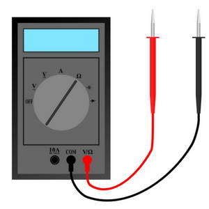
Monitor the output for TRIGGER 1 with a multimeter set to '20VDC', it is recommended that if you have an instrument connected to TRIGGER 1 that it be disconnected for the calibration process.
Apply power to the unit, it will first display the revision number as two patterns of LEDs being the major revision number followed by the minor revision number, it will then display the current TRIGGER mode setting (user or factory default) and will then go into CALIBRATION Mode, indicated by TRIGGER LED 1 turning ON.
(1) This adjustment is used to set the lower voltage level of the output trigger pulse
Adjust P301 to set the lower pulse voltage to the desired level, typically 0V
Press and briefly hold the [LEARN] switch. Release and TRIGGER LED 2 should turn ON.
(2) This adjustment is used to set the higher voltage level of the output trigger pulse
Adjust P401 to set the ‘ON’ trigger pulse voltage to the desired level, typically 10V(*)
Press and briefly hold the [LEARN] switch.
(3) This adjustment defines the pulse-width of the TRIGGER outputs. This should be set to the smallest time period possible consistent with reliable triggering and operation of the attached triggered devices. If the pulse is set too small then some triggered devices may not trigger reliably or some devices may not produce the full `sound’ for which they were designed. Increasing the pulse-width over the optimum period will affect the speed at which MIDI-Retrofit-8 can accept repetitive triggers for the same output. If you do not know the optimal pulse width for your applications we suggest setting it to around 5mS. Setting the pulse-width too wide may result in the loss of MIDI messages and/or false triggers.
-
Monitor the output for TRIGGER 1 using an oscilloscope
-
Adjust P101 to set the desired pulse width

Your unit should now be ready to operate. Apply power and note that the 8x LEDs display a running pattern that indicates the unit is functioning correctly. If the unit has not been through the [LEARN] mode then the pattern will run from the centre triggers [TRIGGER 4] and [TRIGGER 5] to their respective end triggers ([TRIGGER 1] and [TRIGGER 8]) and then back to the centre triggers. If the unit has been through the [LEARN] mode then the pattern will run from [TRIGGER 1] to [TRIGGER 8] and then back to [TRIGGER 1].
MIDI Signal
If you are having problems with the unit not responding to MIDI and you have access to an oscilloscope, then you can (carefully) probe U101_2 and check that you (a) have a signal and (b) that is within specification.
The signal should be sitting, nominally, at 5V and have negative-going pulses when MIDI data is being received. The pulses should have reasonably square edges.
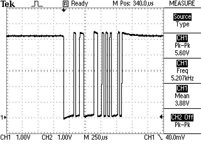
If you are not seeing any pulses, check the wiring of your MIDI IN socket.
(*) The maximum vailable output voltage is dictated by the power supply input voltage. Typically this maximum will be about 3V below the power rail i.e. for a 15VDC power supply the maximum output voltage will be about 12V.

