|
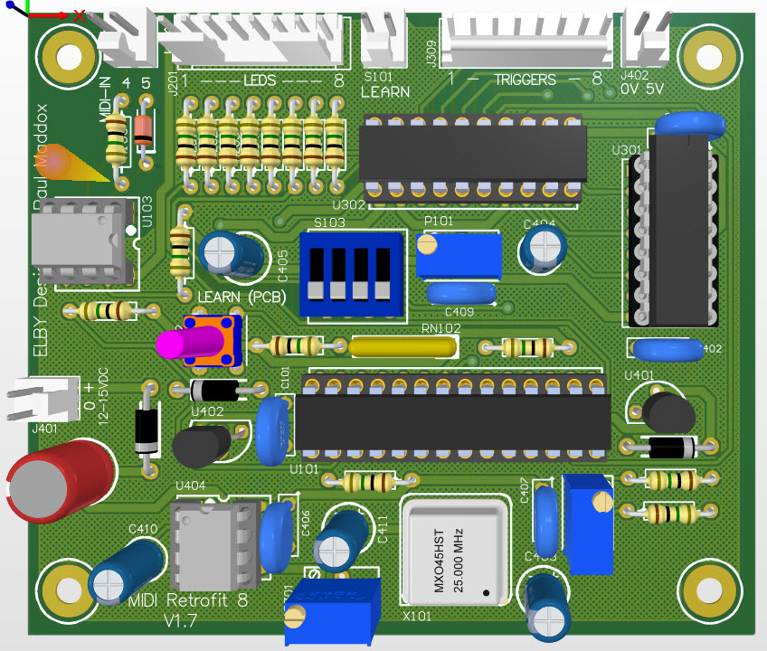
3D Model |
Overlay |
Plan View |
PCB |
|
|
|
Constructors should refer to the Component Overlays along with,
the Bill of Materials for the current value of all components, and
the General Construction Notes for general PCB assembly guidelines.
Construction of the MIDI-Retrofit-8 is pretty straight forward. Attention must be paid, as usual, to the orientation of polarized components and the usual ESD procedures should be in place when handling sensitive components.
But before proceeding with the assembly of the PCB we recommend preparing the enclosure"-
Using the PCB as a template, drill 4x 3.2mm holes near the centre of the base (this already had 4 holes in it for the case securing screw). Thes 4 holes should be countersunk from the outside to allow the supplied M3 bolts to sit flush with the outer face of the base.
Construction of the PCB can then proceed as follows:-
- Dress the MIDI-Retrofit-8 PCB with all components
- Mount C102 across the terminals of S101 on the undeside of the PCB
- Install the board using the four mounting points
- Install all required panel components
- Connect panel components to the board using equipment wiring and the supplied crimp terminals
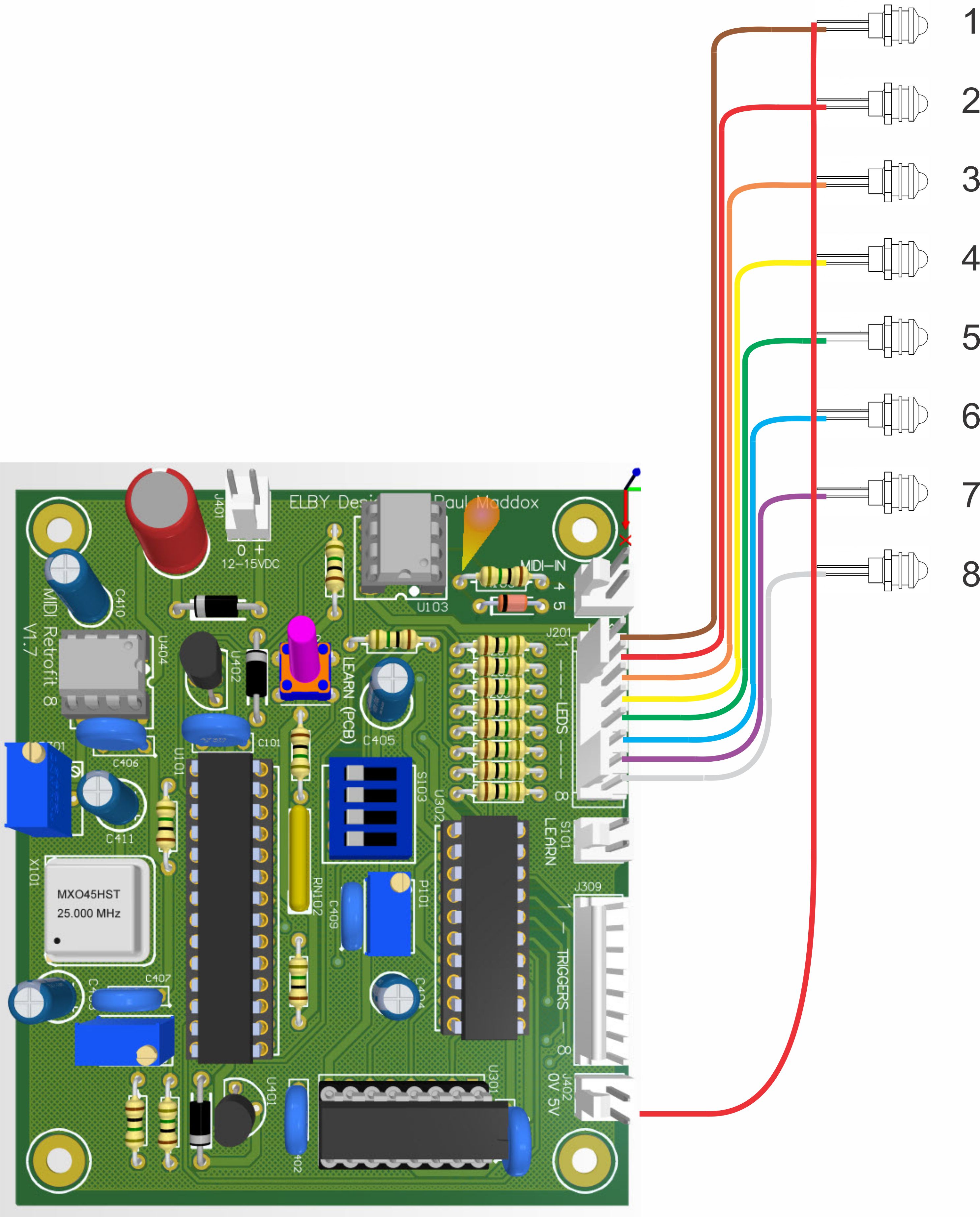
Install the 8-way MTA header for the LEDs as shown at right.
|
|
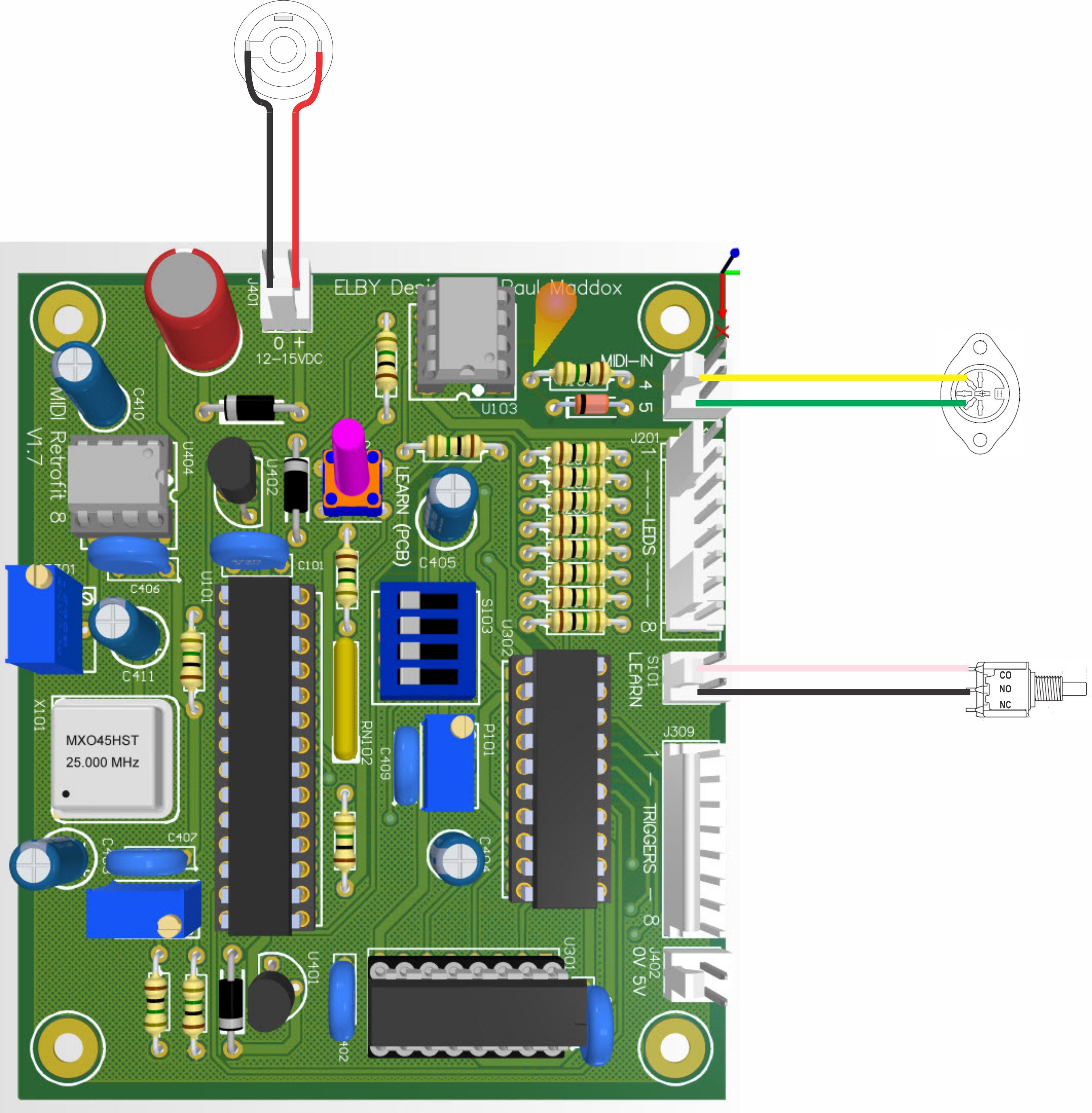
J401 is the power connection for the MIDI-Retrofit-8. The supply should, ideally, be in the range of 12VDC to 15VDC.
J101 is the MIDI IN connector, connect it to J101as shown at right.
Connect the (external) [LEARN] switch to S101 as shown at right. |
|
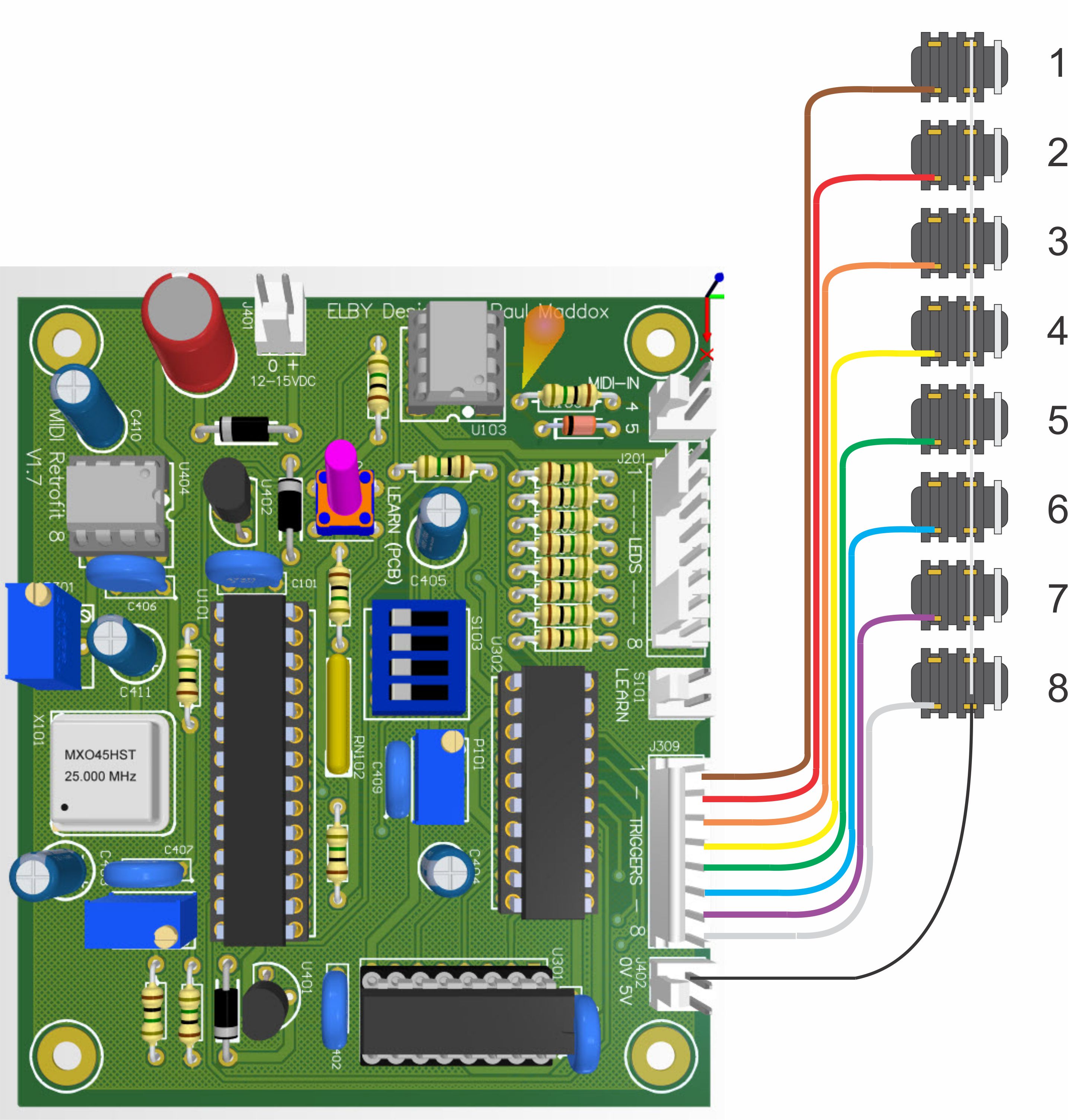
Install the TRIGGER Output jacks terminating their ‘signal’ contacts to J309 as shown at right. Common the SCREEN/SHIELD terminals to J402_1.
|
|
Connect the cathodes of the 8 LEDs to J201 as shown at left. Common all the anodes to J402_2.
|
|