|
3D Model |
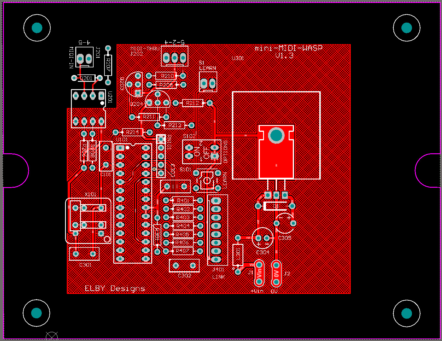
Overlay |
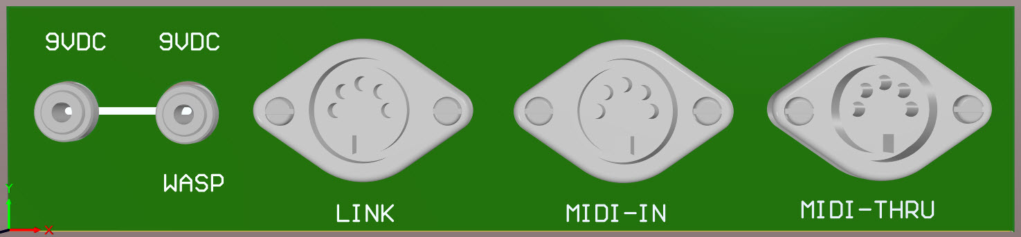
Plan View |
|
|
|
|
Constructors should refer to the Component Overlay along with,
the Bill of Materials for the current value of all components, and
the General Construction Notes for general PCB assembly guidelines.
Start by assembling the PCB. When complete, mount into the base of the enclosure using the tapping screws.
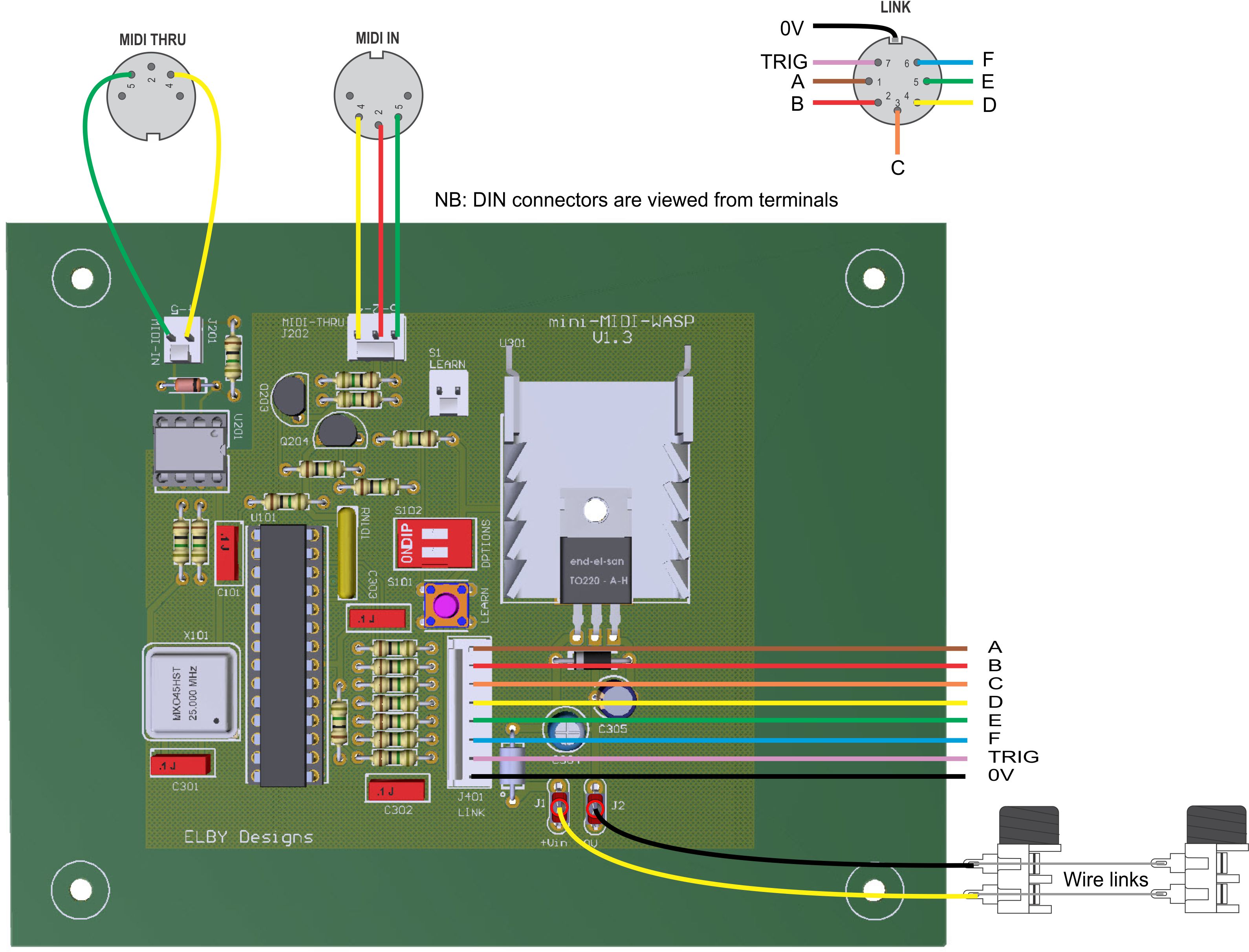
Construction continues with populating the panel. Refer to this wiring diagram:-
Mount all connectors on to the rear panel
DC POWER IN
- Use resistor leg offcuts and connect the 'in' contacts of the DC jacks together
- Strip and twist 2-3mm off one end of the 2 DC-IN leads
- Solder to their respective contacts on one of the jacks
- Strip 5-7mm off the free ends of the 2 DC-IN leads and terminate with quick-connect connectors
- Mount on to their respective tabs (yellow(+V) to J1, black (0V) to J2) on the PCB
MIDI IN & MIDI THRU
- Cut 1x red, 2x yellow and 2x green wires to the length specified
- Strip and twist 2-3mm off one end of each wire
- Solder to their respective pins on the MIDI DIN connectors
- Strip 3-4mm off the free end of each wire, lightly twist and terminate with crimps
- Insert the crimped wires in to the respective MTA housings
- Mount them on to their respective headers (MIDI IN to J201, MIDI THRU to J202) on the PCB
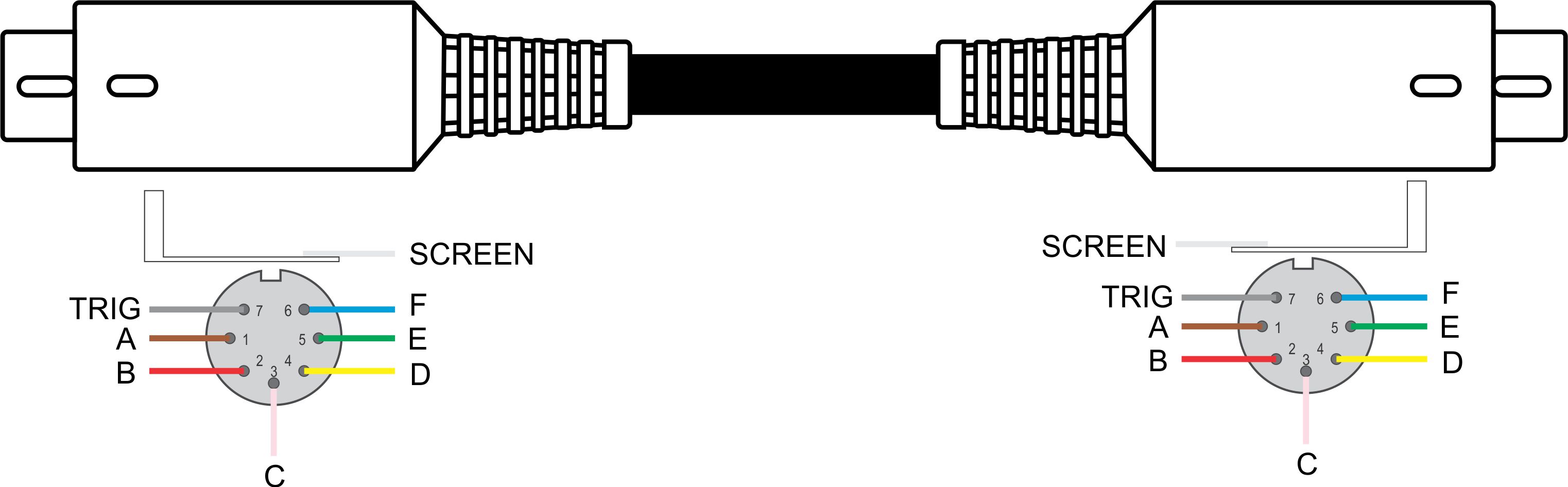
LINK
- Cut the speficied lengths of brown, red, orange, yellow, green, blue & purple wires
- Strip 2-3mm off one end of each of the wires
- Solder to their respective pins on the LINK DIN connector
- Strip 2-3mm off the free end of each wire, lightly twist and terminate with crimps
- Insert the crimped wires in to the J401 MTA housing
- Mount the connector on to J401 on the PCB
Check that all connectors are properly seated on their headers and that all wires are tidily routed around the PCB.
Fit the lid of the enclosure ensuring that you have it correctly orientated with respect to the base.
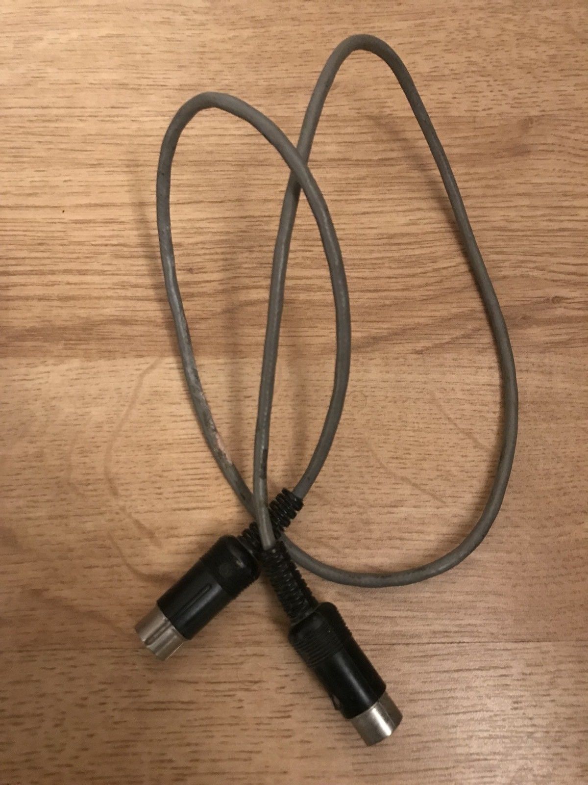
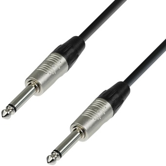
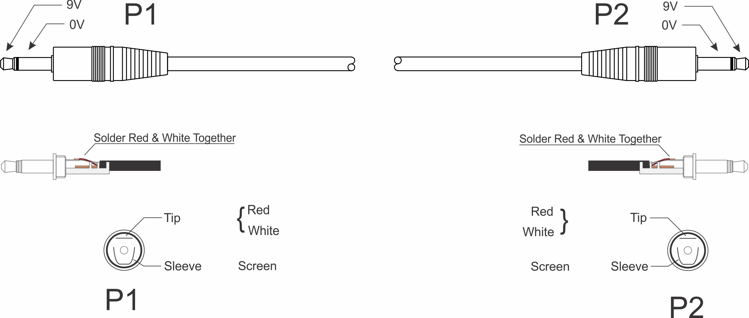
Assemble the LINK Cable following this wiring chart and the DC-DC Power Cable following this wiring chart.

