|
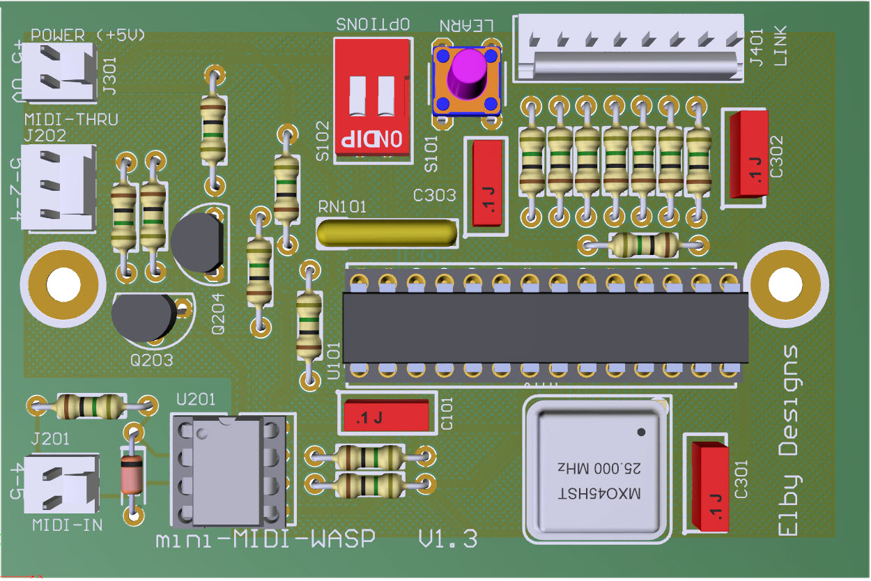
3D Model |
Overlay |
Plan View |
PCB |
|
|
|
Constructors should refer to the Component Overlay along with,
the Bill of Materials for the current value of all components, and
the General Construction Notes for general PCB assembly guidelines.
-
Start by preparing your WASP
-
Place the miniMIDI-WASP PCB in the base of your WASP and mark the 2 mounting points. We recommend the PCB be placed in the back slot of the base of the WASP and positioned centrally between the speaker and panel connections
-
Drill the fixing holes using a 3.2mm drill (approximately 1/8")
-
Fit the 2x M3x25mm Spacers using 2x M3x6mm screws
-
Remove the LINK socket from the WASP front panel and replace it with the 5-pin MIDI-IN socket
-
If required, the MIDI-THRU socket can replace the 2nd LINK connector
|
miniMIDI-WASP location
|
-
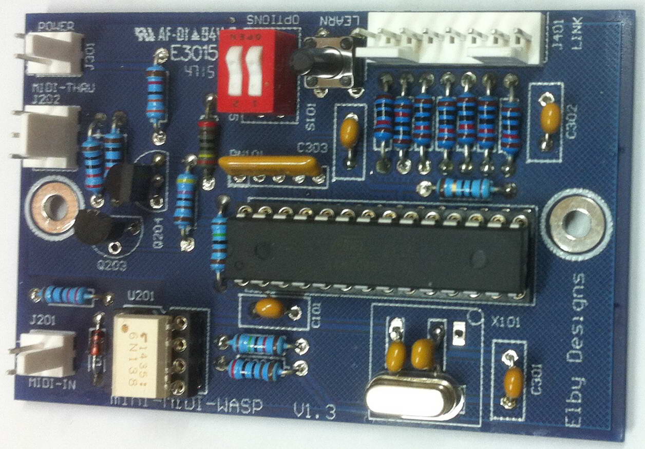
Fit all components to the miniMIDI-WASP PCB paying special attention to the orintation of the crystal X101. The 'dot' on the crystal body should be aligned with the 'dot' on the PCB footprint
-
Strip, twist and crimp one end of each of the supplied cables and mount in to the crimp housings noting the correct sequence of each wire as per the supplied overlay
|
|
-
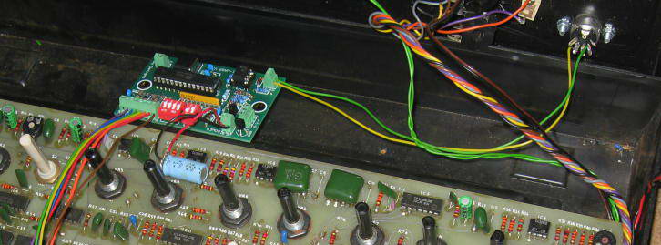
Mount the PCB on to the spacers in the WASP
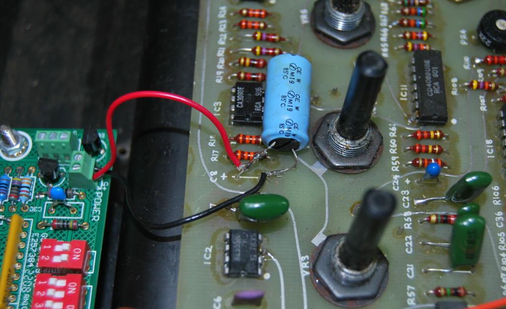
-
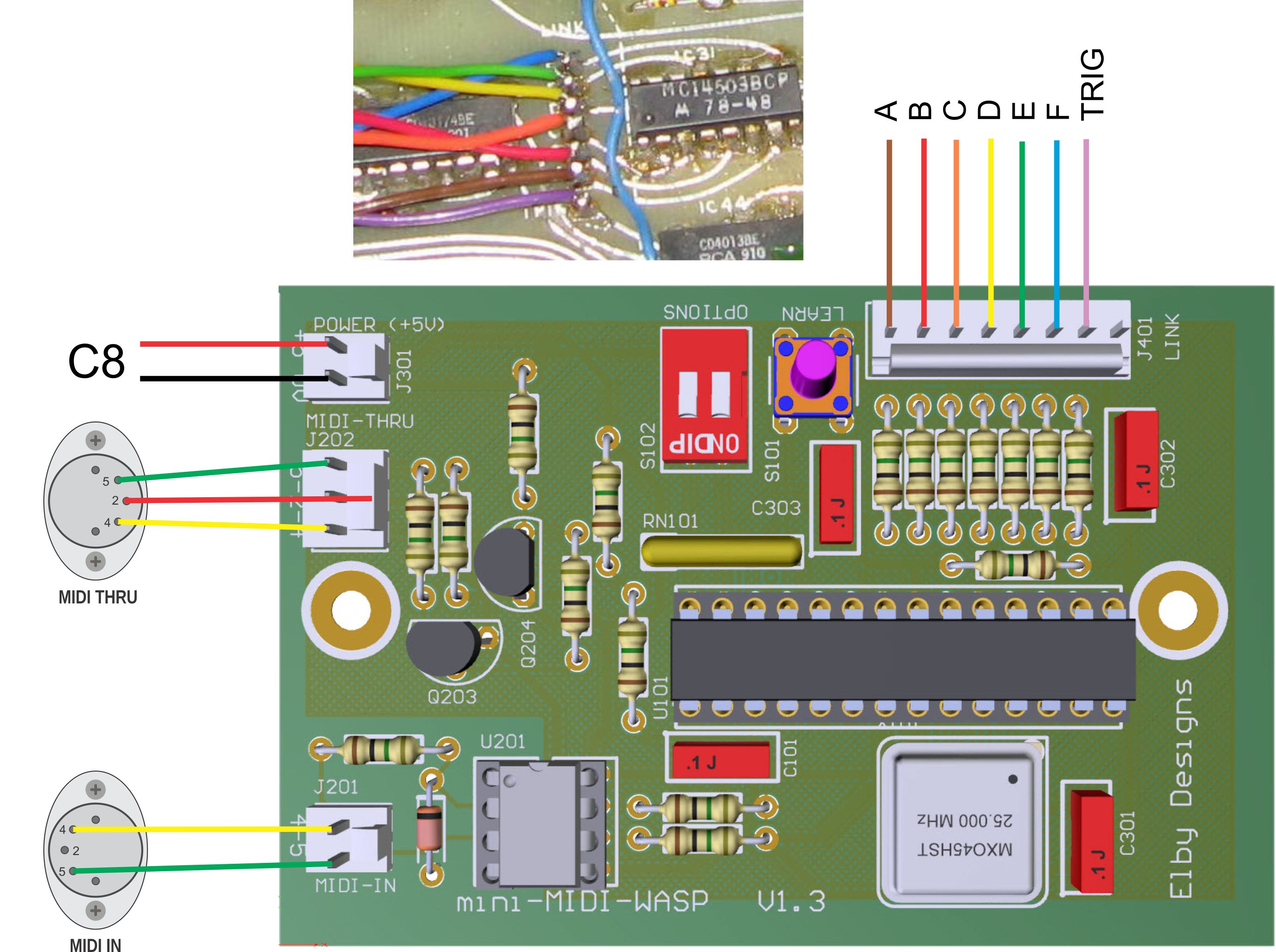
Feed the power wires from J301 to a suitable location on the WASP PCB (we recommend using the large power supply filter capacitor C8 at the top centre edge of the WASP PCB - our picture shows the wires terminated to the capacitor legs on the topside of the PCB but you may need to attch the wires to the underside of the PCB
-
Feed the MIDI-IN wires from J201 to the MIDI-IN socket
-
Cut to length and then strip and twist approximately 3mm from the end of each wire
-
Solder to the MIDI-IN socket following the wiring guide
- Repeat for the MIDI-THRU socket if required
-
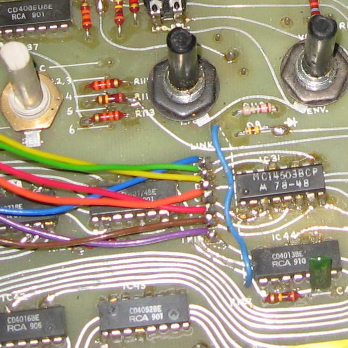
Remove the LINK-TRIG wires from the WASP PCB
-
Feed the wires from J401 to the WASP PCB
-
Cut to length and then strip and twist approximately 2mm from the end of each wire
-
Solder to the LINK pads socket following the wiring guide
Wiring Guide |
Power Wiring
|
LINK Wiring
|
|

