The ASM320 requires 2 adjustments:-
Adjusting the LED indicator.
-
Fit jumper JP1 between pins 1 & 2 (the non-CAL position)
- Set the [RATE (f)] and [RANGE] to a low frequency such that you can see the LED slowly changing in colour/intensity
- Adjust P103 until the LED sweeps equally through both RED and GREEN
Offset Adjustment
- Fit jumper JP1 to the 'CAL' position
- Monitor the [TRIANGLE] output
- The output will tend to drift towards one of the power rails
- Applly a pulse to the [RESET] input
- The output will jump to 0V
- Adjust P102 until the output remains stable at 0V for a period of several seconds
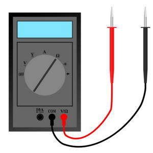
- Repeat steps (4) to (6), progressively switching the multimeter to more sensitive ranges, until the drift is only a few hundred millivolts in several seconds
Careful adjustment of the offset is vital as it determines the minimum frequency at which the ASM320 will operate reliably and the symmetry of the waveforms at low frequencies