|
3D Model |
Overlay |
Plan View |
PCB |
|
|
|
Constructors should refer to the Component Overlays along with,
the Bill of Materials for the current value of all components, and
the General Construction Notes for general PCB assembly guidelines.
- Start assembly with the main board fitting all components except
the valve and switch, D401 and U401
- See Addendum for D401/U401
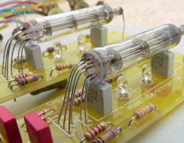
- Refer to picture below. Take the valve and carefully fan the leads
out a few mm. Ensuring that the orientation of the tube leads is
correct, insert the leads in to the PCB and gently feed them
through until the tube is about 3cm above the board
- Start folding the tube over until it is parallel with the board using a
pair of narrow-nose pliers to carefully form the leads as you go.
The tube should finish up about 1cm above the board
- Place the piece of supplied foam on to the marked area on the
PCB and press the tube down against the PCB/foam with a little
firm pressure and solder the leads in to place
- Place the switch on to the PCB and offer up to the front panel
securing it using a couple of jack nuts
- Fit and tighten a nut to the switch ensuring that the switch toggle
action is vertical. When happy, solder in to place
- Assemble the Panther Support board and attach to the module
- Fit the Panther IDC cable to connect the 2 boards
- Finish assembly by adding remaining nuts and knobs.
ADDENDUM
The original CGS765 build used a dual-rail
step-up regulator to generate +/-15VDC from
the +12V rail.
We have subsequently found that reverting back to the systems +/-12V rails provides for more stable operation and so in the current build the
regulator has been bypassed. This requires
the addition of a wire link and a ferrite bead
as shown in the picture below.
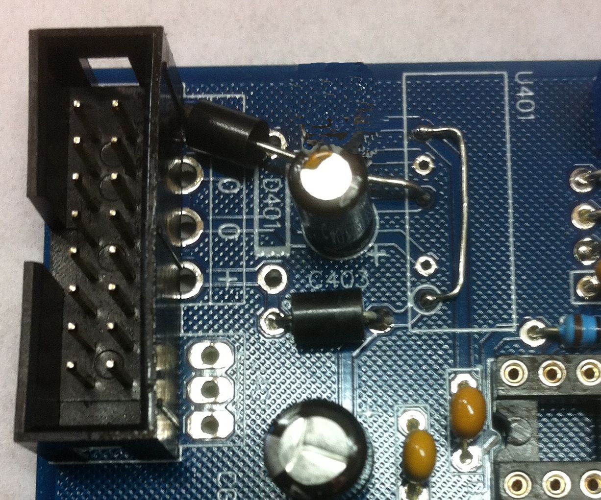
Ensure that when fitting the 2 parts that they
do not short against any exposed parts.


