 |
CGS793 - Trunk Multiples
|
|
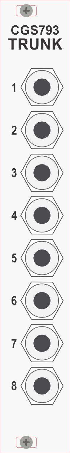 |
The CGS793 can be used to provide trunk lines across your system. With 2 or more joined by a common 'bus cable' the user is able to feed signals in form one point in the system and access them at other points with the big benefit of reducing the number of patch cables running across the front of the system. The CGS793's can be used as non-committed trunk lines or be colour-coded with different jacks to define trunks for CV signals and another, for example, for LOGIC signals. The CGS793 uses a similar same cable configuration as a module power cable i.e 16-pin IDC with odd-number pins being assigned to the 8 panel jacks while the remaining 8 pins provide a 0V seperation between the signals. This does allow a single CGS793 installation to support all signal types with minimal crosstalk although it is recommended to assign LOGIC signals to a separate CGS793 installation. Even if you do pre-assign signal types (and these can be identified by ordering CGS793's with different socket colours (eg Blue for CV, Black for AC and Red for LOGIC) there is nothing to stop you using one or more those for alternate signals if the need arises, as there is no circuitry involved in the CGS793 which are purely passive connections.
Interconnection cables can be simple 1:1 cables as shown at left or multi-drop cables as shown at right. Once installed, each CGS793 installation is akin to have 4 CV/GATE busses running through your system. The simplest installation comprise just 2x CGS793 and a long interconnecting cable allowing one CGS793 to placed at one end of your system and the other at the other end of the system or you coudl have them placed by module groups that are regularly patched such as the CV outputs from a sequencer feeding the CV inputs of a group of VCO's and a 2nd installating feeding LOGIC outputs from the sequencer to the GATE/TRIGGER inputs of a group of envelope shapers.
Example 1 demonstrates the example described above although it has been expanded slightly to help clarify its useage. A 2-CGS793 installation is shown at left connecting the CV outputs of a sequencer being fed to the CV inputs of a group of VCOs. The CGS793s have been colour-coded to ease identification of the trunked connections (Blue/Green = CV IN/OUT). Similarly, a 2nd 2-CGS793 installation has been added at right to connect the LOGIC outputs of a GATE Sequencer to the TRIGGER/GATE inputs of a group of envelope shapers. Again, the CGS793s have been colour-coded to ease identification of the trunked connections (Red/Yellow = LOGIC In/OUT).
Example 2 achieves the same signal routing but this time using a 3-CGS793 multi-drop installation. As a signal on any given socket eg '1' is presented to all the other '1' sockets, the user needs to be more aware of which sockets have been 'committed' to prevent inadvertently patching multiple inputs together or, worse still, multiple outputs. As ribbon cables are not ideal for running between cabinets we recommend using a module such as our ED142. |


|

© Copyright 2000. All rights reserved. Revised: February 3, 2024